
Datasheet


Table Of Contents
- 1. Intended Use
- 2. Installation Requirements
- 3. AC-Input
- 4. Input Inrush Current
- 5. Output
- 6. Hold-up Time
- 7. DC-Input
- 8. Efficiency and Power Losses
- 9. Functional Diagram
- 10. Front Side and User Elements
- 11. Terminals and Wiring
- 12. Lifetime Expectancy and MTBF
- 13. EMC
- 14. Environment
- 15. Protection Features
- 16. Safety Features
- 17. Dielectric Strength
- 18. Approvals
- 19. RoHS, REACH and Other Fulfilled Standards
- 20. Physical Dimensions and Weight
- 21. Accessory
- 22. Application Notes
- 22.1. Peak Current Capability
- 22.2. Back-feeding Loads
- 22.3. Charging of Batteries
- 22.4. External Input Protection
- Parallel Use to Increase Output Power
- Parallel Use for Redundancy
- 22.7. Daisy Chaining of Outputs
- 22.8. Inductive and Capacitive Loads
- Series Operation
- Operation on Two Phases
- 22.11. Use Without PE on the Input
- 22.12. Use in a Tightly Sealed Enclosure
- 22.13. Mounting Orientations
ML60.121
MiniLine-2
12V, 4.5A, SINGLE PHASE INPUT
5. OUTPUT
Output voltage nom. 12V
Adjustment range min. 12-15V guaranteed
max. 16.2V *) at clockwise end position of potentiometer
Factory setting 12.0V ±0.2%, at full load, cold unit
Line regulation max. 10mV 85-264Vac
Load regulation max. 100mV static value, 0A Æ 4.5A
Ripple and noise voltage max. 50mVpp 20Hz to 20MHz, 50Ohm
Output capacitance typ. 3 000μF
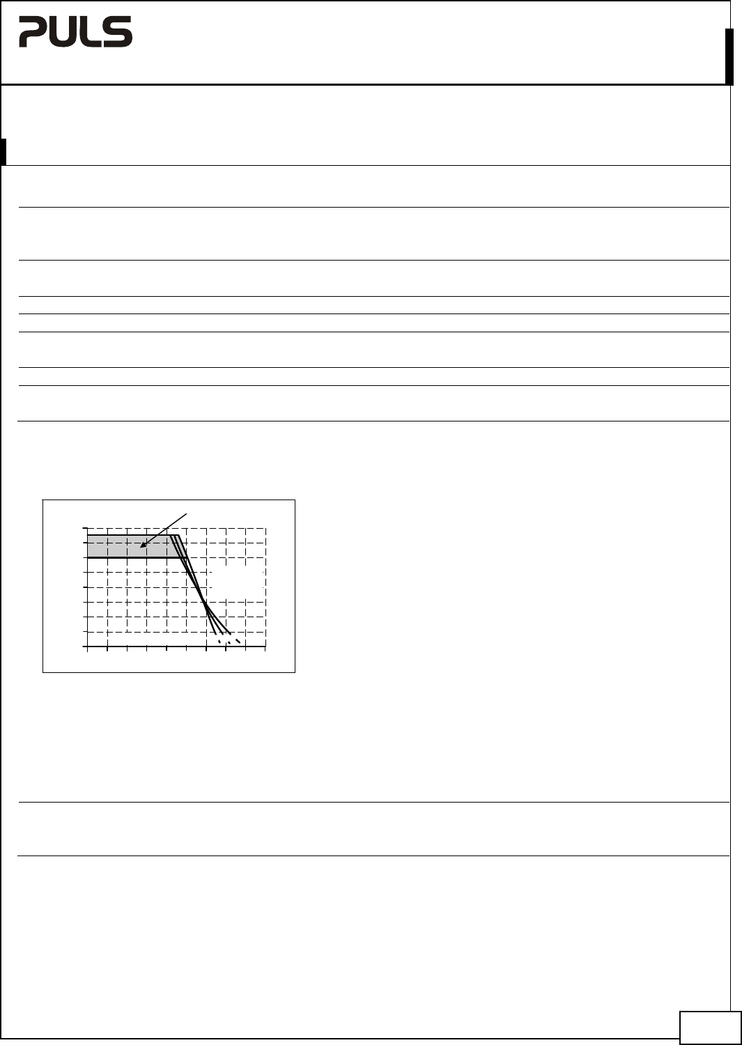
Output current nom. 4.5A at 12V, see Fig. 5-1
nom. 3.6A at 15V, see Fig. 5-1
Output power nom. 54W
Short-circuit current min. 6.0A load impedance 250mOhm, see Fig. 5-1
max. 8.0A load impedance 250mOhm, see Fig. 5-1
*) This is the maximum output voltage which can occur at the clockwise end position of the potentiometer due to tolerances. It is not
guaranteed value which can be achieved. The typical value is about 15.8V.
Fig. 5-1 Output voltage vs. output current,
typ.
Output Voltage
0
0
2
4
6
16V
8
12
14
321 54
10
9A678
Adjustment
Range
Output Current
a) 100Vac
b) 120Vac
c) 230Vac
a
b
c
Peak current capability (up to several milliseconds)
The power supply can deliver a peak current which is higher than the specified short term current. This helps to start
current demanding loads or to safely operate subsequent circuit breakers.
The extra current is supplied by the output capacitors inside the power supply. During this event, the capacitors will be
discharged and causes a voltage dip on the output. Detailed curves can be found in chapter 22.1.
Peak current voltage dips typ. from 12V to 7V at 9A for 50ms, resistive load
typ. from 12V to 5V at 22.5A for 2ms, resistive load
typ. from 12V to 3.2V at 22.5A for 5ms, resistive load
Nov. 2015 / Rev. 1.4 DS--ML60.121-EN
All parameters are specified at 12V, 4.5A, 230Vac 50Hz input, 25°C ambient and after a 5 minutes run-in time unless otherwise noted.
www.pulspower.com Phone +49 89 9278 0 Germany
6/23