
Datasheet


Table Of Contents
- 1. Intended Use
- 2. Installation Requirements
- 3. AC-Input
- 4. Input Inrush Current
- 5. Output
- 6. Hold-up Time
- 7. DC-Input
- 8. Efficiency and Power Losses
- 9. Functional Diagram
- 10. Front Side and User Elements
- 11. Terminals and Wiring
- 12. Lifetime Expectancy and MTBF
- 13. EMC
- 14. Environment
- 15. Protection Features
- 16. Safety Features
- 17. Dielectric Strength
- 18. Approvals
- 19. RoHS, REACH and Other Fulfilled Standards
- 20. Physical Dimensions and Weight
- 21. Accessory
- 22. Application Notes
- 22.1. Peak Current Capability
- 22.2. Back-feeding Loads
- 22.3. Charging of Batteries
- 22.4. External Input Protection
- Parallel Use to Increase Output Power
- Parallel Use for Redundancy
- 22.7. Daisy Chaining of Outputs
- 22.8. Inductive and Capacitive Loads
- Series Operation
- Operation on Two Phases
- 22.11. Use Without PE on the Input
- 22.12. Use in a Tightly Sealed Enclosure
- 22.13. Mounting Orientations
ML60.121
MiniLine-2
12V, 4.5A, SINGLE PHASE INPUT
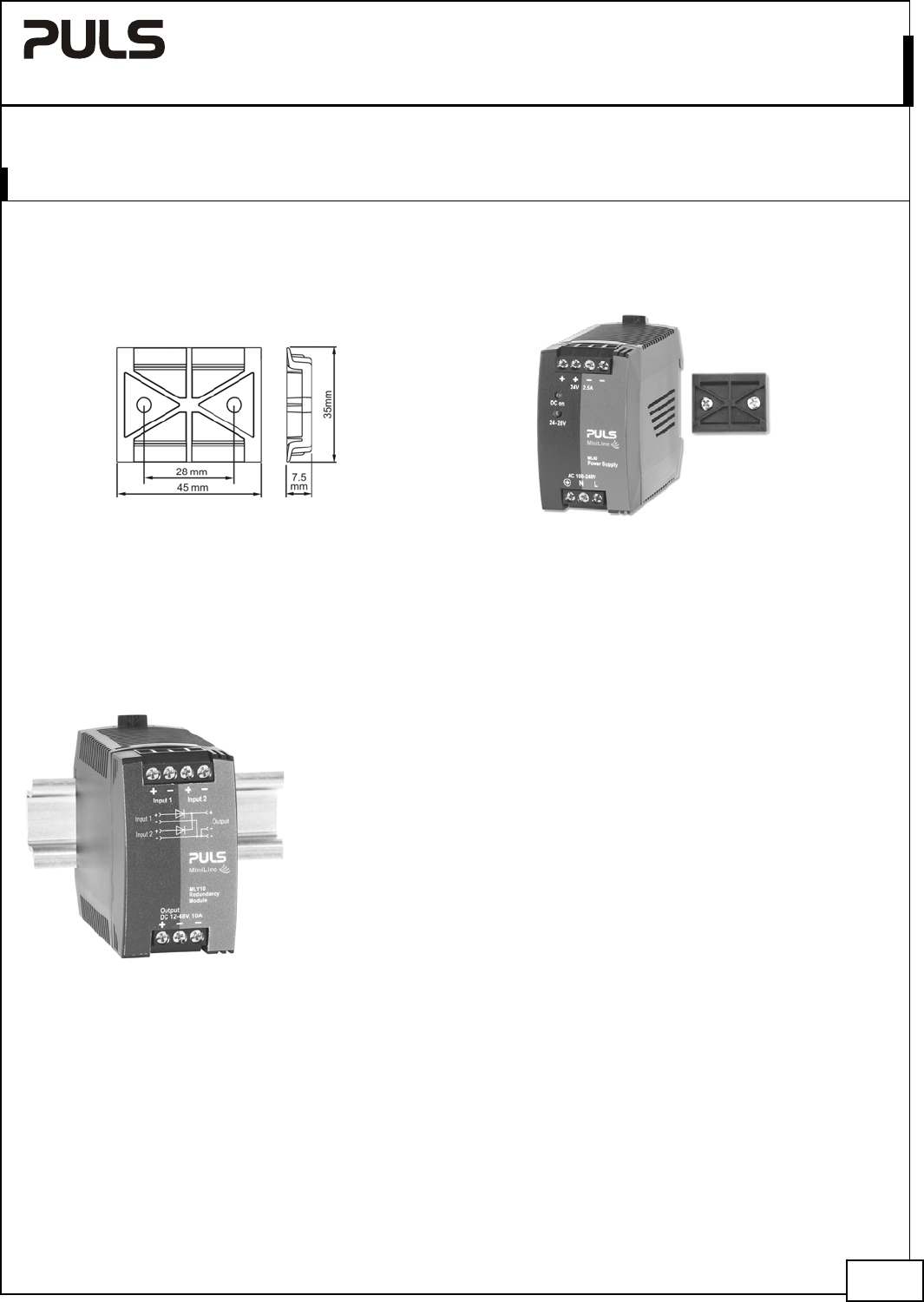
21. ACCESSORY
21.1. ZM3.WALL – WALL MOUNT BRACKET
DIN-Rail bracket for wall or panel mount:
The picture of the power supply is for representation only
Hole diameter: 4.2mm
21.2. MLY10.241 - REDUNDANCY MODULE
The MLY10.241 is a dual redundancy module, which has two diodes with a common cathode included. It can be used
for various purposes. The most popular application is to configure highly reliable
and true redundant power supply systems. Another interesting application is the
separation of sensitive loads from non-sensitive loads. This avoids the distortion
of the power quality for the sensitive loads which can cause controller failures.
Nov. 2015 / Rev. 1.4 DS--ML60.121-EN
All parameters are specified at 12V, 4.5A, 230Vac 50Hz input, 25°C ambient and after a 5 minutes run-in time unless otherwise noted.
www.pulspower.com Phone +49 89 9278 0 Germany
17/23