
User guide

1-Phase Power Supply Instruction Manual
Bedienungsanleitung für 1-Phasen Stromversorgungen
Technical Data
1)
Technische Daten
1)
ML120.241 ML120.244 ML120.CLASS2
Output Voltage Ausgangsspannung nom. DC 24-28V (adjustable) DC 24V (fixed) DC 24V (fixed)
Factory Setting at Full Load Werkseinstellung bei Nennlast typ. 24.1V 24.1V ±3% 24.1V ±3%
Output Current continuous Ausgangsstrom dauernd nom. 5A at 24V, 4.3A at 28V 5A 3.8A
Output Power continuous Ausgangsleistung dauernd nom. 120W 120W 91.2W
Output Ripple & Noise Voltage
13)
Ausgangswelligkeit
13)
max. 50mVpp 50mVpp 50mVpp
Output Overload Behavior Überlastverhalten am Ausgang - continuous current continuous current continuous current
AC Input Voltage AC Eingangsspannung nom. AC 100-120V/ 220-240V
2)
-15%/+10%
AC 200-240V
-15%/+10%
AC 100-120V/ 220-240V
2)
-15%/+10%
Input Frequency Eingangsfrequenz nom.
50-60Hz
±6%
50-60Hz
±6%
50-60Hz
±6%
AC Input Current
3)
AC Eingangsstrom
3)
typ. 1.82A / 1.07A - / 1.07A 1.43A / 0.84A
Power Factor
3)
Leistungsfaktor
3)
typ. 0.62 / 0.54 - / 0.54 0.60 / 0.52
Allowed Voltage L or N to Earth Erlaubte Spannung L oder N zu Erde max. 300Vac 300Vac 300Vac
PFC Norm EN 61000-3-2 Class A PFC Norm EN 61000-3-2 Klasse A - Yes / Ja Yes / Ja Yes / Ja
DC Input Voltage DC Eingangsspannung nom.
DC 290V
-25%/+30%
-
DC 290V
-25%/+30%
Input Inrush Current
3) 4)
Einschaltspitzenstrom
3) 4)
typ. 22A / 33A peak 22A / 33A peak 22A / 33A peak
Hold-up Time
3)
Pufferzeit
3)
typ. 50ms / 50ms - / 35ms 70ms / 68ms
Efficiency
3)
Wirkungsgrad
3)
typ. 88.8% / 90.4% - / 90.3% 88.8% / 90.4%
Power Losses
3)
Verlustleistung
3)
typ. 15.1W / 12.7W - / 12.9W 11.5W / 12.7W
Operational Temperature Range Betriebstemperaturbereich nom. -10°C - +70°C -10°C - +70°C -10°C - +70°C
Output Derating Leistungsrücknahme +60°C to +70°C 3W/°C 3W/°C 0W/°C
Storage Temperature Range Lagertemperaturbereich nom. -40°C - +85°C -40°C - +85°C -40°C - +85°C
Humidity
5)
Feuchte
5)
IEC 60068-2-30 5 - 95% r.H. 5 - 95% r.H. 5 - 95% r.H.
Vibration Schwingen IEC 60068-2-6 2g 2g 2g
Shock Schocken IEC 60068-2-27 15g 6ms, 10g 11ms 15g 6ms, 10g 11ms 15g 6ms, 10g 11ms
Degree of Pollution Verschmutzungsgrad IEC 62103 2
5)
2
5)
2
5)
Degree of Protection Schutzart EN 60529 IP20 IP20 IP20
Class of Protection Schutzklasse IEC 61140 I
6)
I
6)
I
6)
Over-temperature Protection Übertemperaturschutz OTP Yes / Ja Yes / Ja Yes / Ja
Output Over-voltage Protection Überspannungsschutz am Ausgang OVP, max. 32Vdc 33Vdc 29Vdc
Return Voltage Resistance
8)
Rückspeisefestigkeit
8)
max. 35Vdc 35Vdc 35Vdc
Leakage Current
7)
TN/TT-mains
IT-mains
PE- Ableitstrom
7)
TN/TT-Netze
IT-Netze
max.
max.
0.64mA / 0.75mA
1.02mA / 1.45mA
- / 0.75mA
- / 1.45mA
0.64mA / 0.75mA
1.02mA / 1.45mA
Parallel Use
11)
Parallelschaltbar
11)
- Yes / Ja Yes / Ja Yes / Ja
Serial Use
12)
Serienschaltbar
12)
- Yes / Ja Yes / Ja Yes / Ja
Dimensions
9)
(WxHxD) Abmessungen
9)
(BxHxT) nom. 72.5x75x103mm 72.5x75x103mm 72.5x75x103mm
Weight Gewicht max. 360g, 0.8lb 360g, 0.8lb 360g, 0.8lb
Approvals Zulassungen - Æ 10) Æ 10) Æ 10)
Limited Warranty Eingeschränkte Gewährleistung Years / Jahre 3 3 3
1) All parameters are specified at 230Vac input voltage, nominal output current, 25°C ambient
and after a 5 minutes run-in time unless otherwise noted.
2) -Auto-select input
3) at 120Vac / 230Vac
4) Input inrush current is limited with an NTC (temperaturedependend)
5) Do not energize while condensation is present.
6) PE connection required (Ground).
7) Leakage current at 132Vac, 60Hz / 264Vac, 50Hz
8) Loads such as decelerating motors and inductors can feed voltage back to the output of the
power supply. The figure represents the maximum allowed feed back voltage
9) Depth without DIN-rail.
10) See datasheet or markings on the unit.
11) No current share between the units. Allowed up to 45°C ambient temperature. A fuse or diode
on the output of each unit is required if more than three units are connected in parallel.
12) Use only power supplies of the same type. The total output voltage should not be >150Vdc.
13) 50-Ohm measurement, bandwidth 20MHz
1) Alle Werte gelten bei 230Vac Eingangsspannung, Nennausgangsstrom, 25°C Umgebung und
nach einer Aufwärmzeit von 5 Minuten, falls nichts anderes angegeben.
2) -Automatische Bereichswahl
3) bei 120Vac / 230Vac
4) Der Einschaltstromstoß wird mittels NTC begrenzt (temperaturabhängig)
5) Nicht betreiben, solange das Gerät Kondensation aufweist.
6) PE Verbindung erforderlich.
7) Ableitstrom bei 132Vac, 60Hz / 264Vac, 50Hz
8) Bremsende Motoren oder Induktivitäten können Spannung zum Ausgang des Netzteils
rückspeisen. Der Wert gibt die max. zulässige Rückspeisespannung an.
9) Tiefe ohne DIN-Schiene
10) Siehe Datenblatt oder Prüfzeichen auf dem Gerät.
11) Keine Stromaufteilung zwischen den Geräten. Erlaubt bis max. 45°C. Eine Sicherung oder
Diode je Ausgang ist erforderlich wenn mehr als 3 Geräte parallel geschaltet werden.
12) Nur für gleiche Geräte bis zu einer Gesamtspannung von 150Vdc
13) 50-Ohm Messung, Bandbreite 20MHz
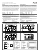
Installation
Use DIN-rails according to EN 60715 with a height of 7.5 or 15mm. Mounting orientation must be
input terminal located at the bottom and output at the top. For other orientations see datasheet.
Do not obstruct air flow as the unit is convection cooled. Ventilation grid must be kept free of any
obstructions. The following installation clearances must be kept when power supplies are
permanently fully loaded:
Left / right: 5mm (15mm in case the adjacent device is a heat source)
40mm on top, 20mm on the bottom of the unit.
Use in hazardous location areas
Units which are marked with "Class I Div 2" are suitable for use in Class I Division 2 Groups A, B,
C, D locations.
WARNING EXPLOSION HAZARDS!
Substitution of components may impair suitability for this environment. Do not disconnect the unit
or operate the voltage adjustment unless power has been switched off or the area is known to be
non-hazardous. A suitable enclosure must be provided for the end product which has a minimum
protection of IP54 and fulfils the requirements of the EN 60079-15:2010.
Installation
Geeignet für DIN-Schienen entsprechend EN 60715 mit einer Höhe von 7,5 oder 15mm. Der
Einbau hat so zu erfolgen, dass sich die Eingangsklemmen unten und die Ausgangsklemmen
oben befinden. Für andere Einbaulagen siehe Datenblatt. Luftzirkulation nicht behindern! Das
Gerät ist für Konvektionskühlung ausgelegt. Es ist für ungehinderte Luftzirkulation zu sorgen.
Folgende Einbauabstände sind bei dauerhafter Volllast einzuhalten:
Links / rechts: 5mm (15mm bei benachbarten Wärmequellen)
Oben: 40mm, unten 20mm vom Gerät.
Betrieb in explosionsgefährdeter Umgebung
Geräte, die mit "Class I Div 2" gekennzeichnet sind, sind für den Einsatz in Klasse I Division 2
Gruppen A,B,C,D Umgebung geeignet.
ACHTUNG EXPLOSIONSGEFAHR!
Veränderungen am Gerät können die Tauglichkeit für diese Umgebung beeinträchtigen.
Anschlüsse nicht abklemmen und Spannungseinstellung nicht verändern, solange Spannung
anliegt oder die Umgebung als explosionsgefährlich gilt. Das Gerät muss mindestens in ein IP54
Gehäuse, welches den Anforderungen der EN 60079-15:2010 entspricht, eingebaut werden.
CE Marking
CE mark is in conformance with EMC directive 2004/108/EC, the low-voltage directive (LVD)
2006/95/EC and the RoHS directive 2011/65/EC.
EMC Immunity: EN 61000-6-1, EN 61000-6-2
EMC Emission EN 61000-6-3, EN 61000-6-4, FCC Part 15 Class B
CE Kennzeichnung
Das CE Zeichen ist angebracht und erklärt die Erfüllung der EMV Richtlinie 2004/108/EG, der
Niederspannungsrichtlinie 2006/95/EG und der RoHS Richtlinie 2011/65/EG.
Störfestigkeit: EN 61000-6-1, EN 61000-6-2
Störaussendung: EN 61000-6-3, EN 61000-6-4, FCC Part 15 Klasse B