
User manual


CD5.241, CD5.241-S1
CD–Series
DC/DC Converter; 24V, 5A
Jan. 08 / Rev. 1.1 DS-CD5.241-EN / All parameters are specified at 24V, 5A and 24Vdc input at 25°C ambient unless otherwise noted.
www.pulspower.com Phone +49 89 9278 0 Germany
8/22
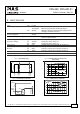
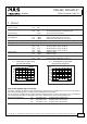
10. FUNCTIONAL DIAGRAM
Fig. 10-1 Functional diagram CD5.241
+
+
-
-
V
OUT
Input Fuse
&
Input Filter
Output
Voltage
Regulator
Power
Converter
Output
Filter
DC
ok
Output
Over-
Voltage
Protection
Reverse
Polarity
Protection
&
Inrush
Limiter
Chassis
Ground
+
-
Over-
Temperature
Protection
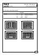
Fig. 10-2 Functional diagram CD5.241-S1
+
+
-
-
V
OUT
Input Fuse
&
Input Filter
Output
Voltage
Regulator
Power
Converter
Output
Filter
DC
ok
Output
Over-
Voltage
Protection
Reverse
Polarity
Protection
&
Inrush
Limiter
Chassis
Ground
+
-
Over-
Temperature
Protection
DC-ok
Relay
Output
Voltage
Monitor
13
14
Input
low
Relay
11
12
Input
Voltage
Monitor
Input
low
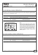
11. RELIABILITY
CD5.241 CD5.241-S1
Lifetime expectancy min. 183 000h 180 000h 40°C, 24V, 2.5A
min. 65 000h 60 000h 40°C, 24V, 5A
min. 37 000h 33 000h 40°C, 24V, 6A
min. 185 000h 169 000h 25°C, 24V, 5A
MTBF SN 29500, IEC 61709 1 178 000h 1 048 000h 40°C, 24V, 5A
1 932 000h 1 719 000h 25°C, 24V, 5A
MTBF MIL HDBK 217F 625 000h 602 000h 40°C, 24V, 5A, Ground Benign GB40
838 000h 807 000h 25°C, 24V, 5A, Ground Benign GB25
The Lifetime expectancy shown in the table indicates the operating hours (service life) and is determined by the
lifetime expectancy of the built-in electrolytic capacitors. Lifetime expectancy is specified in operational hours.
Lifetime expectancy is calculated according to the capacitor’s manufacturer specification. The prediction model allows
a calculation of up to 15 years from date of shipment.
MTBF stands for Mean Time Between Failure, which is calculated according to statistical device failures, and indicates
reliability of a device. It is the statistical representation of the likelihood of a unit to fail and does not necessarily
represent the life of a product.