
Datasheet


CD5.121
CD-Series
DC/DC Converter 12V, 8A
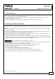
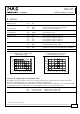
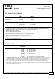
8. FUNCTIONAL DIAGRAM
Fig. 8-1 Functional diagram
+
+
-
-
V
OUT
Input Fuse
&
Input Filter
Output
Voltage
Regulator
Power
Converter
Output
Filter
DC
ok
Output
Over-
Voltage
Protection
Reverse
Polarity
Protection
&
Inrush
Limiter
Chassis
Ground
+
-
Over-
Temperature
Protection
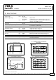
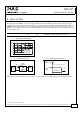
9. FRONT SIDE AND USER ELEMENTS
Fig. 9-1 Front side
A
Input terminals
Screw terminals
+ Positive input
- Negative (return) input
Chassis ground: can be used to bond the housing to PE
Ground this terminal to minimize high-frequency emissions.
B
Output terminals
Screw terminals, dual terminals per pole, both pins are equal
+ Positive output
- Negative (return) output Screw terminals
C
Output voltage potentiometer
Open the flap to set the output voltage. Factory set: 12.0V
D
DC-OK LED (green)
On when the voltage on the output terminals is > 8.5V
Oct 2009 / Rev. 1.3 DS-CD5.121-EN
All parameters are specified at 12V, 8A, 24Vdc input voltage, 25°C ambient and after a 5 minutes run-in time unless otherwise noted.
www.pulspower.com Phone +49 89 9278 0 Germany
9/21