
Datasheet


CD5.121
CD-Series
DC/DC Converter 12V, 8A
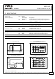
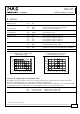
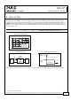
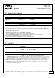
10. TERMINALS AND WIRING
Input Output
Type screw terminals screw terminals
Solid wire 0.5-6mm
2
0.5-6mm
2
Stranded wire 0.5-4mm
2
0.5-4mm
2
American Wire Gauge 20-10 AWG 20-10 AWG
Wire stripping length 7mm / 0.275inch 7mm / 0.275inch
Screwdriver 3.5mm slotted or
Pozidrive No 2
3.5mm slotted or
Pozidrive No 2
Recommended tightening torque 1Nm, 9lb.in 1Nm, 9lb.in
Instructions:
a) The external circuitry of all terminals must meet the safety requirements stipulated by IEC/EN/UL 60950-1: SELV.
b) Use appropriate copper cables that are designed for an operating temperature of:
60°C for ambient up to 45°C and
75°C for ambient up to 60°C minimum.
c) Follow national installation codes and installation regulations!
d) Ensure that all strands of a stranded wire enter the terminal connection!
e) Up to two stranded wires with the same cross section are permitted in one connection point.
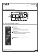
f) Do not load the terminals with more than 25A! See section 22.9
g) Screws of unused terminal compartments should be securely tightened.
h) Ferrules are allowed, but not required
11. RELIABILITY
Input 24Vdc
Lifetime expectancy
*) 173 000h at 12V, 4A and 40°C
63 000h at 12V, 8A and 40°C
35 000h at 12V, 9.6A and 40°C
179 000h at 12V, 8A and 25°C
MTBF
**) SN 29500, IEC 61709 1 161 000h at 12V, 8A and 40°C
1 904 000h at 12V, 8A and 25°C
MTBF
**) MIL HDBK 217F 610 000h at 12V, 8A and 40°C; Ground Benign GB40
817 000h at 12V, 8A and 25°C; Ground Benign GB25
*) The Lifetime expectancy shown in the table indicates the minimum operating hours (service life) and is determined by the lifetime
expectancy of the built-in electrolytic capacitors. Lifetime expectancy is specified in operational hours and is calculated according to the
capacitor’s manufacturer specification. The prediction model allows only a calculation of up to 15 years from date of shipment.
**) MTBF stands for Mean Time Between Failure, which is calculated according to statistical device failures, and indicates reliability of a
device. It is the statistical representation of the likelihood of a unit to fail and does not necessarily represent the life of a product.
The MTBF figure is a statistical representation of the likelihood of a device to fail. A MTBF figure of e.g. 1 000 000h means that
statistically one unit will fail every 100 hours if 10 000 units are installed in the field. However, it can not be determined if the failed unit
has been running for 50 000h or only for 100h.
Oct 2009 / Rev. 1.3 DS-CD5.121-EN
All parameters are specified at 12V, 8A, 24Vdc input voltage, 25°C ambient and after a 5 minutes run-in time unless otherwise noted.
www.pulspower.com Phone +49 89 9278 0 Germany
10/21