
User manual

CS5.244
C–Series
24V, 5A, SINGLE PHASE INPUT
Dec. 2006 / Rev. 1.1 DS-CS5.244-EN
All parameters are specified at 24V, 5A, 230Vac, 25°C ambient and after a 5 minutes run-in time unless otherwise noted.
www.pulspower.com Phone +49 89 9278 0 Germany
8/20
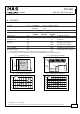
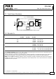
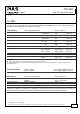
11. FUNCTIONAL DIAGRAM
Fig. 11-1 Functional diagram
+
+
-
-
V
OUT
Input Fuse
&
Input Filter
Output
Voltage
Regulator
Power
Converter
Output
Filter
DC
ok
L
N
Output
Over-
Voltage
Protection
Input
Rectifier
&
Inrush
Limiter
(NTC)
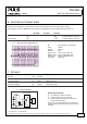
12. RELIABILITY
AC 100V AC 120V AC 230V
Lifetime expectancy min. - - 72 000h 40°C, 24V, 5A
min. - - 42 000h 40°C, 24V, 6A
min. - - 144 000h 40°C, 24V, 2,5A
min. - - 15 years 25°C, 24V, 5A
MTBF SN 29500, IEC 61709 - - 940 000h 40°C, 24V, 5A
- - 799 000h 40°C, 24V, 6A
- - 1 626 000h 25°C, 24V, 5A
MTBF MIL HDBK 217F - - 680 000h 40°C, 24V, 5A, Ground Benign GB40
- - 612 000h 40°C, 24V, 6A, Ground Benign GB40
- - 932 000h 25°C, 24V, 5A, Ground Benign GB25
The Lifetime expectancy shown in the table indicates the operating hours (service life) and is determined by the
lifetime expectancy of the built-in electrolytic capacitors.
Lifetime expectancy is specified in operational hours. Lifetime expectancy is calculated according to the capacitor’s
manufacturer specification. The prediction model allows a calculation of up to 15 years from date of shipment.
MTBF stands for Mean Time Between Failure, which is calculated according to statistical device failures, and indicates
reliability of a device. It is the statistical representation of the likelihood of a unit to fail and does not necessarily
represent the life of a product.