
User manual
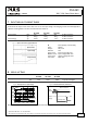

CS3.241
C–Series
24V, 3.3A, SINGLE PHASE INPUT
September. 2007 / Rev. 1.1 DS-CS3.241-EN
All parameters are specified at 24V, 3.3A, 230Vac, 25°C ambient and after a 5 minutes run-in time unless otherwise noted.
www.pulspower.com Phone +49 89 9278 0 Germany
8/21
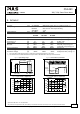
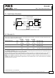
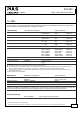
11. FUNCTIONAL DIAGRAM
Fig. 11-1 Functional diagram
+
+
-
-
V
OUT
Input Fuse
&
Input Filter
Output
Voltage
Regulator
Power
Converter
Output
Filter
DC
ok
L
N
Output
Over-
Voltage
Protection
Input
Rectifier
&
NTC Inrush
Limiter
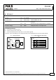
12. RELIABILITY
These units are extremely reliable and use only the highest quality materials. The number of critical components such
as electrolytic capacitors has been reduced.
AC 100V AC 120V AC 230V
Lifetime expectancy min. 57 000h 64 000h 77 000h 40°C, 24V, 3.3A
min. t.b.d. t.b.d. t.b.d. 40°C, 24V, 1.65A
min. 160 000h >15 years >15 years 25°C, 24V, 3.3A
MTBF SN 29500, IEC 61709 t.b.d. t.b.d. t.b.d. 40°C, 24V, 3.3A
t.b.d. t.b.d. t.b.d. 25°C, 24V, 3.3A
MTBF MIL HDBK 217F t.b.d. t.b.d. t.b.d. 40°C, 24V, 3.3A, Ground Benign GB40
t.b.d. t.b.d. t.b.d. 25°C, 24V, 3.3A, Ground Benign GB25
The Lifetime expectancy shown in the table indicates the operating hours (service life) and is determined by the
lifetime expectancy of the built-in electrolytic capacitors.
Lifetime expectancy is specified in operational hours. Lifetime expectancy is calculated according to the capacitor’s
manufacturer specification. The prediction model allows a calculation of up to 15 years from date of shipment.
MTBF stands for Mean Time Between Failure, which is calculated according to statistical device failures, and indicates
reliability of a device. It is the statistical representation of the likelihood of a unit to fail and does not necessarily
represent the life of a product.