
Data Sheet
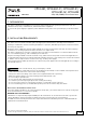


Table Of Contents
- 1. Intended Use
- 2. Installation Requirements
- 3. AC-Input
- 4. DC-Input
- 5. Input Inrush Current
- 6. Output
- 7. Hold-up Time
- 8. DC-OK Relay Contact
- 9. Efficiency and Power Losses
- 10. Lifetime Expectancy
- 11. MTBF
- 12. Terminals and Wiring
- 13. Functional Diagram
- 14. Front Side and User Elements
- 15. EMC
- 16. Environment
- 17. Protection Features
- 18. Safety Features
- 19. Dielectric Strength
- 20. Approvals
- 21. Other Fulfilled Standards
- 22. Physical Dimensions and Weight
- 23. Accessories
- 24. Application Notes
- 24.1. Peak Current Capability
- 24.2. Back-feeding Loads
- 24.3. External Input Protection
- 24.4. Output Circuit Breakers
- Series Operation
- Parallel Use to Increase Output Power
- 24.7. Parallel Use for Redundancy
- 24.8. Inductive and Capacitive Loads
- 24.9. Charging of Batteries
- Operation on Two Phases
- 24.11. Use in a Tightly Sealed Enclosure
- 24.12. Mounting Orientations

CP10.241, CP10.241-C1, CP10.241-S1,
CP10.241-S2, CP10.242
CP-Series
24V, 10A, 240W, SINGLE PHASE INPUT
Aug. 2017 / Rev. 1.4a DS-CP10.241-EN
All values are typical at 24V, 10A, 230Vac, 50Hz, 25°C ambient and after a 5 minutes run-in time unless otherwise noted.
www.pulspower.com Phone +49 89 9278 0 Germany
8. DC-OK RELAY CONTACT
This feature monitors the output voltage on the output terminals of a running power supply.
Contact closes As soon as the output voltage reaches typ. 90% of the adjusted output voltage level.
Contact opens As soon as the output voltage dips more than 10% below the adjusted output voltage.
Short dips will be extended to a signal length of 100ms. Dips shorter than 1ms will be ignored.
Switching hysteresis 1V
Contact ratings Maximal 60Vdc 0.3A, 30Vdc 1A, 30Vac 0.5A, resistive load
Minimal permissible load: 1mA at 5Vdc
Isolation voltage See dielectric strength table in section 18.
Fig. 8-1 DC-ok relay contact behavior
100ms
0.9* V
ADJ
<
1ms
10%
open
V
OUT
= V
ADJ
openclosed closed
>
1ms
9/30