
Data Sheet
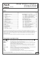
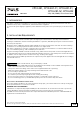


Table Of Contents
- 1. Intended Use
- 2. Installation Requirements
- 3. AC-Input
- 4. DC-Input
- 5. Input Inrush Current
- 6. Output
- 7. Hold-up Time
- 8. DC-OK Relay Contact
- 9. Efficiency and Power Losses
- 10. Lifetime Expectancy
- 11. MTBF
- 12. Terminals and Wiring
- 13. Functional Diagram
- 14. Front Side and User Elements
- 15. EMC
- 16. Environment
- 17. Protection Features
- 18. Safety Features
- 19. Dielectric Strength
- 20. Approvals
- 21. Other Fulfilled Standards
- 22. Physical Dimensions and Weight
- 23. Accessories
- 24. Application Notes
- 24.1. Peak Current Capability
- 24.2. Back-feeding Loads
- 24.3. External Input Protection
- 24.4. Output Circuit Breakers
- Series Operation
- Parallel Use to Increase Output Power
- 24.7. Parallel Use for Redundancy
- 24.8. Inductive and Capacitive Loads
- 24.9. Charging of Batteries
- Operation on Two Phases
- 24.11. Use in a Tightly Sealed Enclosure
- 24.12. Mounting Orientations

CP10.241, CP10.241-C1, CP10.241-S1,
CP10.241-S2, CP10.242
CP-Series
24V, 10A, 240W, SINGLE PHASE INPUT
Aug. 2017 / Rev. 1.4a DS-CP10.241-EN
All values are typical at 24V, 10A, 230Vac, 50Hz, 25°C ambient and after a 5 minutes run-in time unless otherwise noted.
www.pulspower.com Phone +49 89 9278 0 Germany
Fig. 3-3 Input current vs. output current at
24V output voltage
Fig. 3-4 Power factor vs. output current at
24V output voltage
12A
123456789
0
0.5
1.0
1.5
2.0
2.5
3A
Input Current, typ.
10 11
a) 100Vac
b) 120Vac
c) 230Vac
b
a
c
Output Current
Power Factor, typ.
123456789 12A
0.75
0.8
0.85
0.9
0.95
1.0
10 11
Output Current
(a) 100Vac,
(b) 120Vac,
(c) 230Vac
(a)
(b)
(c)
4. DC-INPUT
DC input Nom. DC 110-150V ±20%
For CP10.241, CP10.241-C1, CP10.241-S1, CP10.241-
S2
Nom. DC 110-300V ±20%
For CP10.242
DC input range Min. 88-180Vdc For CP10.241, CP10.241-C1, CP10.241-S1,
CP10.241-S2, continuous operation
Min. 88-360Vdc For CP10.242
DC input current Typ. 2.35A At 110Vdc, at 24V, 10A
Typ. 0.84A At 300Vdc, at 24V, 10A
Allowed Voltage L/N to Earth Max. 375Vdc Continuous, according to IEC 62477-1
Turn-on voltage Typ. 80Vdc Steady state value
Shut-down voltage Typ. 70Vdc Steady state value
Typ. 55Vdc Dynamic value for maximal 250ms
Fig. 4-1 Wiring for DC Input
Instructions for DC use:
+
-
Load
L
PE
+
-
Power Supply
AC
DC
Battery
N
a) Use a battery or a similar DC source. A supply from the
intermediate DC-bus of a frequency converter is not
recommended and can cause a malfunction or damage
the unit.
b) Connect +pole to L and –pole to N.
c) Connect the PE terminal to an earth wire or to the
machine ground.
5/30