
Datasheet
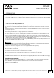
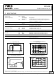


Table Of Contents
- 1. Intended Use
- 2. Installation Requirements
- 3. Input Voltage
- 4. Soft-start and Input Inrush Current Surge
- 5. Output
- 6. Hold-up Time
- 7. Efficiency and Power Losses
- 8. Functional Diagram
- 9. Front Side and User Elements
- 10. Terminals and Wiring
- 11. Reliability
- 12. EMC
- 13. Environment
- 14. Protection Features
- 15. Safety Features
- 16. Dielectric Strength
- 17. Approvals
- 18. RoHS, REACH and Other Fulfilled Standards
- 19. Physical Dimensions and Weight
- 20. Accessories
- 21. Application Notes
- 21.1. Peak Current Capability
- 21.2. Back-feeding Loads
- 21.3. Inductive and Capacitive Loads
- 21.4. Charging of Batteries
- 21.5. External Input Protection
- 21.6. Requirements for the Supplying Source
- Parallel Use to Increase Output Power
- 21.8. Parallel Use for Redundancy
- 21.9. Daisy Chaining of Outputs
- Series Operation
- 21.11. Use in a Tightly Sealed Enclosure
- 21.12. Mounting Orientations
CD5.242
CD-Series
DC/DC Converter 24V, 5A
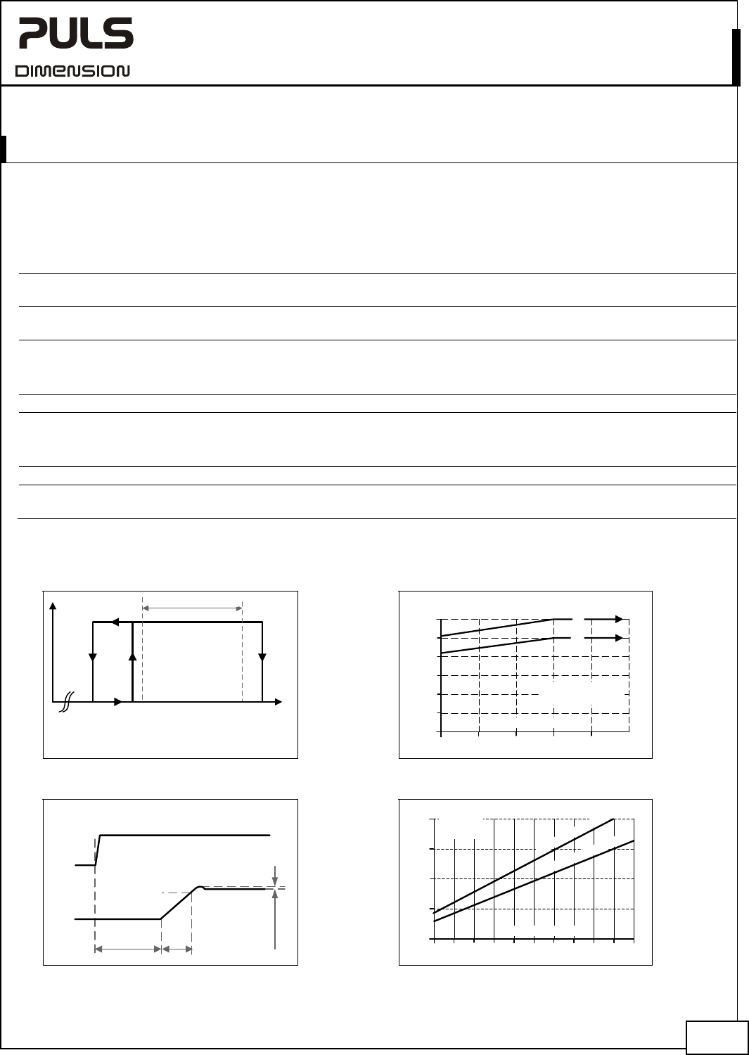
3. INPUT VOLTAGE
Input voltage nom. DC 48V
Input voltage range 36.0-60.0Vdc full specified
30.5-36.0Vdc maximal 60 seconds or with de-rating see Fig. 3-2
max. 63.0Vdc absolute maximum continuous input voltage with no
damage to the DC/DC converter
Allowed voltage between input
and earth
max. 60Vdc or
42.2Vac
in case the output voltage is not grounded.
Allowed input ripple voltage
max. 5Vpp 47Hz-500Hz, the momentary input voltage must always
be within the specified limits.
Turn-on voltage typ. 34.5Vdc steady-state value, see Fig. 3-1
Shut-down voltage typ. 30.5Vdc steady-state value, see Fig. 3-1
typ. 63.5Vdc steady-state value, see Fig. 3-1
Input current typ. 2.75A at 48Vdc input and output 24V, 5A, see Fig. 3-4
Start-up delay typ. 670ms see Fig. 3-3
Rise time typ. 80ms 0mF, 24V, constant current load 5A, see Fig. 3-3
typ. 150ms 5mF, 24V, constant current load 5A, see Fig. 3-3
Turn-on overshoot max. 500mV see Fig. 3-3
Input capacitance typ. 800μF external capacitors on the input voltage bus are allowed
without any limitations.
Fig. 3-1 Input voltage range
Fig. 3-2 Allowable output current below 36V
input voltage
Turn-on
34.5Vdc
V
IN
P
OUT
Shut-down
60.0Vdc
30.5Vdc
36.0Vdc
Rated input range
63.5Vdc
0
1
2
3
4
6A
30 32 34 36 40Vdc
Input Voltage
Output Current
5
38
(
a
)
(
b
)
(a) Ambient < 45°C
(b) Ambient < 60°C
Fig. 3-3 Turn-on behavior, definitions Fig. 3-4 Input current vs. output load
4/22
Start-up
delay
Rise
Time
Ov
6A
ershoot
- 5%
Output
Voltage
Input
Voltage
1
1.5 2 3
4
0
1
2
3
4A
5
Output Current
2.5
3.5
4.5
5.5
I
n
p
u
t
:
4
8
Vd
c
Input
Current,
typ.
I
n
p
u
t
:
3
6
V
d
c
Mar. 2016 / Rev. 1.5 DS-CD5.242-EN
All parameters are specified at 24V, 5A, 48Vdc input voltage, 25°C ambient and after a 5 minutes run-in time unless otherwise noted.
www.pulspower.com Phone +49 89 9278 0 Germany