
Data Sheet
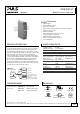
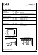

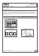


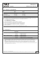
Table Of Contents
- 1. Intended Use
- 2. Installation Requirements
- 3. Input Voltage
- 4. Soft-start and Input Inrush Current Surge
- 5. Output
- 6. Hold-up Time
- 7. Efficiency and Power Losses
- 8. Functional Diagram
- 9. Front Side and User Elements
- 10. Terminals and Wiring
- 11. Reliability
- 12. EMC
- 13. Environment
- 14. Protection Features
- 15. Safety Features
- 16. Dielectric Strength
- 17. Approvals
- 18. RoHS, REACH and Other Fulfilled Standards
- 19. Physical Dimensions and Weight
- 20. Accessories
- 21. Application Notes
- 21.1. Peak Current Capability
- 21.2. Back-feeding Loads
- 21.3. Inductive and Capacitive Loads
- 21.4. External Input Protection
- 21.5. Requirements for the Supplying Source
- 21.6. Parallel Use to Increase Output Power
- 21.7. Parallel Use for Redundancy
- 21.8. Series Operation
- 21.9. Charging of Batteries
- 21.10. Use in a Tightly Sealed Enclosure
- 21.11. Mounting Orientations

CD5.241-L1
CD-Series
DC/DC Converter 24V, 3.8A
8. FUNCTIONAL DIAGRAM
Fig. 8-1 Functional diagram
+
+
-
-
Input Fuse
&
Input Filter
Power
Converter
Output
Filter
DC
ok
Output
Over-
Voltage
Protection
Reverse
Polarity
Protection
&
Inrush
Limiter
Chassis
Ground
+
-
Over-
Temperature
Protection
9. FRONT SIDE AND USER ELEMENTS
Fig. 9-1 Front side
A Input terminals
Screw terminals
+ Positive input
- Negative (return) input
Chassis ground: can be used to bond the housing to PE
Ground this terminal to minimize high-frequency emissions.
B
Output terminals
Screw terminals, dual terminals per pole, both pins are equal
+ Positive output
- Negative (return) output Screw terminals
C
DC-OK LED (green)
On when the voltage on the output terminals is > 21V
Mar. 2016 / Rev. 1.2 DS-CD5.241-L1-EN
All parameters are specified at 24V, 3.8A, 24Vdc input voltage, 25°C ambient and after a 5 minutes run-in time unless otherwise noted.
www.pulspower.com Phone +49 89 9278 0 Germany
9/21