
Data Sheet
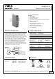
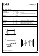

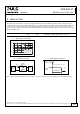


Table Of Contents
- 1. Intended Use
- 2. Installation Requirements
- 3. Input Voltage
- 4. Soft-start and Input Inrush Current Surge
- 5. Output
- 6. Hold-up Time
- 7. Efficiency and Power Losses
- 8. Functional Diagram
- 9. Front Side and User Elements
- 10. Terminals and Wiring
- 11. Reliability
- 12. EMC
- 13. Environment
- 14. Protection Features
- 15. Safety Features
- 16. Dielectric Strength
- 17. Approvals
- 18. RoHS, REACH and Other Fulfilled Standards
- 19. Physical Dimensions and Weight
- 20. Accessories
- 21. Application Notes
- 21.1. Peak Current Capability
- 21.2. Back-feeding Loads
- 21.3. Inductive and Capacitive Loads
- 21.4. External Input Protection
- 21.5. Requirements for the Supplying Source
- 21.6. Parallel Use to Increase Output Power
- 21.7. Parallel Use for Redundancy
- 21.8. Series Operation
- 21.9. Charging of Batteries
- 21.10. Use in a Tightly Sealed Enclosure
- 21.11. Mounting Orientations

CD5.241-L1
CD-Series
DC/DC Converter 24V, 3.8A
5. OUTPUT
Output voltage nom. 24V
Adjustment range min. - not adjustable
Factory setting 24.1V ±0.2%, at full load, cold unit
Line regulation max. 25mV Input voltage variations between 18 to 32.4Vdc
Load regulation max. 100mV static value, 0A Æ 3.8A
Ripple and noise voltage max. 50mVpp 20Hz to 20MHz, 50Ohm
Output current nom. 3.8A see Fig. 5-1
Output power nom. 92W
Short-circuit current min. 3A continuous current, short circuit impedance 200mOhm
max. 6A continuous current, short circuit impedance 200mOhm
Output capacitance typ. 2 200μF
Fig. 5-1 Output voltage vs. output current,
typ.
Fig. 5-2 Current limitation vs. input voltage,
(23V constant voltage load), typ.
Output Voltage
0
6/21
024
4
8
12
28V
16
20
24
6
A
31 5
Output Current
Output Current
3.8
14 18 22
3.9
4.0
4.1
4.3A
32Vd242016
4.2
26 28 30
3.7
Input Voltage
c
Peak current capability (up to several milliseconds)
The DC/DC converter can deliver a peak current, which is higher than the specified short term current. This helps to
start current demanding loads or to safely operate subsequent circuit breakers.
The extra current is supplied by the output capacitors inside the DC/DC converter. During this event, the capacitors will
be discharged and causes a voltage dip on the output. Detailed curves can be found in chapter 21.1.
Peak current voltage dips typ. from 24V to 16V at 7.6A for 50ms, resistive load
typ. from 24V to 12.5V at 15.2A for 2ms, resistive load
typ. from 24V to 8.5V at 15.2A for 5ms, resistive load
Mar. 2016 / Rev. 1.2 DS-CD5.241-L1-EN
All parameters are specified at 24V, 3.8A, 24Vdc input voltage, 25°C ambient and after a 5 minutes run-in time unless otherwise noted.
www.pulspower.com Phone +49 89 9278 0 Germany