
Data Sheet
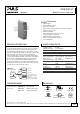
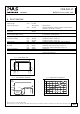

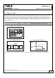


Table Of Contents
- 1. Intended Use
- 2. Installation Requirements
- 3. Input Voltage
- 4. Soft-start and Input Inrush Current Surge
- 5. Output
- 6. Hold-up Time
- 7. Efficiency and Power Losses
- 8. Functional Diagram
- 9. Front Side and User Elements
- 10. Terminals and Wiring
- 11. Reliability
- 12. EMC
- 13. Environment
- 14. Protection Features
- 15. Safety Features
- 16. Dielectric Strength
- 17. Approvals
- 18. RoHS, REACH and Other Fulfilled Standards
- 19. Physical Dimensions and Weight
- 20. Accessories
- 21. Application Notes
- 21.1. Peak Current Capability
- 21.2. Back-feeding Loads
- 21.3. Inductive and Capacitive Loads
- 21.4. External Input Protection
- 21.5. Requirements for the Supplying Source
- 21.6. Parallel Use to Increase Output Power
- 21.7. Parallel Use for Redundancy
- 21.8. Series Operation
- 21.9. Charging of Batteries
- 21.10. Use in a Tightly Sealed Enclosure
- 21.11. Mounting Orientations

CD5.241-L1
CD-Series
DC/DC Converter 24V, 3.8A
10. TERMINALS AND WIRING
Input Output
Type spring-clamp terminals spring-clamp terminals
Solid wire max. 6mm
2
max. 6mm
2
Stranded wire max. 4mm
2
max. 4mm
2
American Wire Gauge 20-10 AWG 20-10 AWG
Wire stripping length 10mm / 0.4inch 10mm / 0.4inch
Instructions:
a) The external circuitry of all terminals must meet the safety requirements stipulated by IEC/EN/UL 60950-1: SELV.
b) Use appropriate copper cables that are designed for an operating temperature of:
60°C for ambient up to 45°C and
75°C for ambient up to 60°C minimum
90°C for ambient up to 70°C minimum.
c) Follow national installation codes and installation regulations!
d) Ensure that all strands of a stranded wire enter the terminal connection!
e) Screws of unused terminal compartments should be securely tightened.
f) Screws of unused terminal compartments should be securely tightened.
g) Ferrules are allowed.
h) Do not connect or disconnect the wires from the terminals below -25°C (-13°F).
11. RELIABILITY
Input 24Vdc
Lifetime expectancy
*) 228 000h at 24V, 1.9A and 40°C
134 000h at 24V, 3.8A and 40°C
378 000h at 24V, 3.8A and 25°C
MTBF **) SN 29500, IEC 61709 1 487 000h at 24V, 3.8A and 40°C
2 534 000h at 24V, 3.8A and 25°C
MTBF
**) MIL HDBK 217F 665 000h at 24V, 3.8A and 40°C; Ground Benign GB40
937 000h at 24V, 3.8A and 25°C; Ground Benign GB25
*) The Lifetime expectancy shown in the table indicates the minimum operating hours (service life) and is determined by the lifetime
expectancy of the built-in electrolytic capacitors. Lifetime expectancy is specified in operational hours and is calculated according to the
capacitor’s manufacturer specification. The prediction model allows only a calculation of up to 15 years from date of shipment.
**) MTBF stands for Mean Time Between Failure, which is calculated according to statistical device failures, and indicates reliability of a
device. It is the statistical representation of the likelihood of a unit to fail and does not necessarily represent the life of a product.
The MTBF figure is a statistical representation of the likelihood of a device to fail. A MTBF figure of e.g. 1 000 000h means that
statistically one unit will fail every 100 hours if 10 000 units are installed in the field. However, it can not be determined if the failed unit
has been running for 50 000h or only for 100h.
Mar. 2016 / Rev. 1.2 DS-CD5.241-L1-EN
All parameters are specified at 24V, 3.8A, 24Vdc input voltage, 25°C ambient and after a 5 minutes run-in time unless otherwise noted.
www.pulspower.com Phone +49 89 9278 0 Germany
10/21