TS-9720EN Series Progressive Scan Shutter Cameras Operation Manual 10157 Rev.
i Notice Page Notice The material contained in this manual consists of information that is proprietary to JAI PULNiX, Inc., and may only be used by the purchasers of the product. JAI PULNiX, Inc. makes no warranty for the use of its product and assumes no responsibility for any errors which may appear or for damages resulting from the use of the information contained herein. JAI PULNiX, Inc. reserves the right to make changes without notice.
Page ii Table of Contents 1 Introduction . . . . . . . . . . . . . . . . . . . . . . . . . . . . . . . . . . . . . . . 1 2 Getting Started. . . . . . . . . . . . . . . . . . . . . . . . . . . . . . . . . . . . . 3 1.1 1.2 1.3 1.4 2.1 2.2 Scope of this Manual . . . . . . . . . . . . . . . . . . . . . . . . . . . . . . . . . . Related Documents . . . . . . . . . . . . . . . . . . . . . . . . . . . . . . . . . . . Key Functions of the TS-9720EN Camera . . . . . . . . . . . . . . . . . .
Page iii Table of Contents 5.4 6 Attaching the Camera Lens . . . . . . . . . . . . . . . . . . . . . . . . . . . . .35 Camera Features . . . . . . . . . . . . . . . . . . . . . . . . . . . . . . . . . 36 6.1 6.2 6.3 Progressive scanning . . . . . . . . . . . . . . . . . . . . . . . . . . . . . . . . . .36 Asynchronous Reset . . . . . . . . . . . . . . . . . . . . . . . . . . . . . . . . . .36 ADR (Automatic Dynamic Range) Control . . . . . . . . . . . . . . . . . .38 6.3.1 6.3.2 6.3.3 6.4 6.
Page iv List of Figures FIGURE 1. Typical Equipment Setup . . . . . . . . . . . . . . . . . . . . . . . . . . . . . . . . . . . . . . . . 3 FIGURE 2. User Administration . . . . . . . . . . . . . . . . . . . . . . . . . . . . . . . . . . . . . . . . . . . . 6 FIGURE 3. Properties . . . . . . . . . . . . . . . . . . . . . . . . . . . . . . . . . . . . . . . . . . . . . . . . . . . . 7 FIGURE 4. Camera Properties . . . . . . . . . . . . . . . . . . . . . . . . . . . . . . . . . . . . . . . . . . . . .
Page v List of Tables TABLE 1. Firmware Names and Descriptions . . . . . . . . . . . . . . . . . . . . . 23 TABLE 2. 12-Pin Connector . . . . . . . . . . . . . . . . . . . . . . . . . . . . . . . . . . 32 TABLE 3. D-Sub Connector Pinout Configurations (10226-6212 VC) . . . 32 TABLE 4. 10/100 BaseT Ethernet Pinout Configuration. . . . . . . . . . . . . . 33 TABLE 5. Exposure Times . . . . . . . . . . . . . . . . . . . . . . . . . . . . . . . . . . . . 38 TABLE 6.
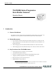
December 15, 2005 TS-9720EN Series Progressive Scan Shutter Cameras Operation Manual 1 Introduction 1.1 Scope of this Manual This manual covers the operation of the TS-9720EN/TSC-9720EN traffic control camera.* For information on how to operate the associated software, please see the software manual. 1.2 Related Documents • Lane Controller to Ethernet Network Camera Interface Document, doc. number 69-1198 • Vehicle Imaging System 300 (VISCAM300) Camera Hardware Interface Definitions, doc.
Page 2 Introduction • Static/DHCP support for TCP/IP configuration • Image transfer over Ethernet using FTP over TCP/IP • Frame date/time stamp facility with user-definable text strings • High quality JPEG encoding • Automatic dynamic range control and maximum contrast images using the optional Smart Light Sensor 1.
Page 3 Getting Started 2 Getting Started 2.1 Required Equipment FIGURE 1. Typical Equipment Setup EN1 * 1P1 PC EN2 * 1P2 EN3 * 1P2 Cat5e/6 Ethernet cable Cat5e/6 Ethernet cable Ethernet switch EN setup software *Each camera requires a PD-12 12-V power supply. For details, please see “Power Supplies and Cable Setup.” • PD-12 power supply • Cat5e/6 Ethernet cable • 10/100/1 G Ethernet switch • Debug-232 serial/power cable (JAI PULNiX part number 31013219) 2.2 Network Settings 2.2.
Page 4 Getting Started 2.2.2 Changing the IP Address of the TS-9720EN Camera If you need to change the IP address of your TS-9720EN camera, you can do so using either the EN setup software or the debug RS-232 serial/power cable. Choose the method that is most appropriate for your application, and follow the steps listed. 2.2.2 (a) Changing the IP Address of the TS-9720EN Camera Using the EN Setup Software You can use the EN setup software to change the IP address of the TS-9720EN camera.
Page 5 Getting Started Password: Password Once you log in as Administrator, you can create a new user and set a custom password. To set the properties of each camera connected to the network, follow the steps below: 1. Click the “Properties” button. The software will automatically find all EN cameras currently on the network. 2. Select the EN camera you want to see in the left window. All accessible registers are displayed in the right window. 3. Click the “Video” button.
Page 6 Tutorial 3 Tutorial This section demonstrates typical operations of the EN camera that most applications will require. This tutorial is intended for first-time users of the EN camera. Go through this section step by step to familiarize yourself with the EN’s operations. 3.1 Image Capturing 3.1.1 Start Up the EN Setup Software Find the “EN Setup” shortcut on your desktop or go to “Start” -> “All Programs” -> “EN Setup” -> “EN Setup.” Start the “EN Setup” software.
Page 7 Tutorial 3.1.2 FIGURE 3. Camera Properties Properties BW EN cameras Color EN cameras Click the camera icon on the left side of the window to see all the config/status registers accessible.
Page 8 Tutorial FIGURE 4. Camera Properties 3.1.3 Live Image Capturing/Focusing Click the “Video” button. Highlight the icon of the camera you want to see. Click the “Full Size” and “Live” video buttons. You will now see a live video image. The live image is generated by an internal trigger mechanism inside the EN camera. This internal trigger is independent of either FTP or message-based TCP image. Also, during live image display, Flash is disabled at nighttime.
Page 9 Tutorial FIGURE 5. Live Image Capturing Use the “Focus Bar” button to make precise adjustments to the lens focus.
Page 10 Tutorial FIGURE 6. Focus Bar Use the “Measuring Box” button to make sure the license plate or particular target is in the correct side of the video field of view.
Page 11 Tutorial FIGURE 7. Measuring Box Position The “Half Size” image button is useful for situations in which two EN cameras together cover a single lane. Using the “Half Size” image button to capture two images: one on the left side of camera1, the other on the right side of camera2. To activate “Half Size,” click on the camera icon and drag it to either the left or right video frame. Click the “Live” button to see the live image. Use the focus tool to make precise adjustments to the lens focus.
Page 12 Tutorial FIGURE 8. Half Size Image Position Click the “Quad Size” image button to capture four images. Each image will then be reduced from the full 768 x 484 resolution to 384 x 242 resolution. Click and drag the camera icon to the desired quad image frame. Click the “Live” button to see a live image.
Page 13 Tutorial FIGURE 9. “Quad Size” Image Button Three trigger-sniffing modes are available: “One,” “All,” and “Last.” “One” trigger mode is for when you want the EN camera to take a single shot of video image, as soon as it receives a valid TTL trigger, Ethernet trigger, or RS-485 serial trigger. “All” trigger mode is continuous trigger-sniffing mode.
Page 14 Tutorial The “HW Trigger” and “Rep. Trigger” buttons send the Ethernet trigger command to the EN camera. “HW Trigger” button sends a single Ethernet trigger command. “Rep. Trigger” sends a continuous Ethernet trigger command every second. 3.1.4 Image Properties You can monitor the image properties of captured images, whether it’s “Live,” “Snap,” or “Trigger Sniffing” mode. On the Video Window menu, select “Image Properties” under “View.
Page 15 Tutorial 3.2 Image Transfer 3.2.1 FTP Image Transfer To transfer images via FTP, first make sure to set up the FTP server properly. Please check the following items: The username/password or anonymous login must be set for FTP server. Set the permission of the read/write/create directory. First, type the IP address of the FTP server (destination IP). If you have a second FTP server, enter that IP address as well.
Page 16 Tutorial 3.3 ADR (Automatic Dynamic Range) Control 3.3.1 Light Sensor Connection ADR control is a process that runs inside the EN camera. It controls the camera every 1/10 second to ensure that when the camera is triggered, it produces a high quality image of the license plate and the vehicle it is mounted on, in all ambient lighting conditions. The ADR also decides when to turn on/off auxiliary lighting as required to maintain proper plate illumination at night and during dawn/dusk transitions.
Page 17 Tutorial You can connect up to two light sensors. If two IP addresses and port numbers are identical, then the EN camera tries to connect only a single light sensor. Set the ADR Control register from “Manual” to “ADR Control (Using the Light Sensor).” This will activate the connection to the light sensor. If the connection is successful, you should see a live data change in the ADR Debug side A/B registers. Also, you should see what camera parameters ADR decides to set.
Page 18 Tutorial Generate an Ethernet trigger or input TTL trigger to see Flash. The “Live” or “Snap” button does not generate Flash, because they are independent from normal trigger operation. Normally, Flash and Night Light are controlled by ADR and a light sensor. To take advantage of this feature, connect to the light sensor. Set the “Flash Auto/Manual” and “Night Light Control” registers as shown below.
Page 19 Tutorial 3.4 Time Synchronization The EN camera supports NTP (network time protocol) synchronization. If you disable NTP by clearing the “NTP Client Control” register, then the internal clock will drift approximately 1.5 seconds per day. To reset the clock, set the “Real Time Clock” register to your current local time. If you decide to take advantage of the NTP feature, make sure to set up the NTP server, preferably with GPS input. This guarantees that the clock drift is within 10ms.
Page 20 Tutorial 3.5 Static IP Address Assignment The factory default IP assignment is static IP= 10.0.0.65. The user must change the IP address of the camera. There are four methods to change the static IP address: EN setup software, Telnet,serial terminal using the debug RS-232 serial/power cable, and BIOS/Monitor using the debug RS-232 serial/ power cable.
Page 21 Tutorial Reboot the camera. In the next power-up, the camera will get the IP address dynamically from the DHCP server.
Page 22 Tutorial 3.6 Maintenance 3.6.1 Debug Counters For debugging purposes, some status registers are available as debug counters. Detailed information for each debugging counter is included in the LC-EN Interface document. This tutorial covers the following debug counters. • Trigger Filter Noise count = number of hardware TTL triggers that failed trigger noise filter. • PRE Filter Noise count • POST Filter Noise count = number of hardware TTL triggers that failed POST filter.
Page 23 Tutorial By generating an Ethernet trigger (“All” and “HW Trigger” button on the EN setup video window), you can see only VINIT and IRQ counters are incrementing. This is because the first four counters are only for the hardware TTL trigger. By feeding the hardware TTL trigger, you can see “Valid Trigger count,” “VINIT count” and “IRQ count” register incrementing.
Page 24 Tutorial TABLE 1. Firmware Names and Descriptions (Continued) Firmware Name Description Filename conversion OS Image Real-time Linux OS image vmlinux_YYMMDDVR.osi Lib/Drv file Library and driver package libdrv_YYMMDDVR.drv Camera Module H8 firmware h8cpu_YYMMDDVR.pat If you want to update multiple cameras at the same time, use the SHIFT key to highlight multiple cameras. Then, right-click to select “Update Firmware in Camera(s).” 3.6.
Page 25 Tutorial The first method requires setting the Hyperterminal to the following setting (9600-8-N-1. No hardware handshake). Power up the EN camera. You should see the monitor message in the serial terminal. Type the “/” key within three seconds.
Page 26 Tutorial After typing the “/” key, you should see the following monitor menu. Enter “3” to select “Change IP addresses” mode. Enter “1” to select Ethernet interface 1. Enter “1” again to select “Change local address.” Enter the new IP address. After setting the new IP address, type “0” to exit the monitor menu. After the boot-up sequence, login to the serial terminal.
Page 27 Tutorial Type “en -v > version.txt.” View the content of “version.txt” to see the firmware version. Enter the command “ps” to see what processes are running. If the “dhcpc” daemon is running, kill this process. To do so, enter, for example, “kill .” Enter the command “ifconfig” to see if the network is up and running. Eth0 is the network interface of the EN camera. In the above example, the EN’s network is set to the following: IP address = 10.0.0.65. Subnet mask = 255.255.255.0.
Page 28 Tutorial Enter the command “ifconfig eth0 netmask .” This is a temporary IP assignment because the EN camera will lose this setting once you restart it. Now you should be able to telnet to the EN cameras. If you want to assign the new IP address permanently, you can use the “test_libcamera” utility. The “test_libcamera” utility allows access to EEPROM, where all network settings are saved.
Page 29 Uploading the Firmware 4 Uploading the Firmware There are five pieces of firmware inside the EN camera that you can upload over the Ethernet. They are: EN_APP: OS_Image: Lib/drV: FPGA Bitfile: H8: top-level application software. Linux OS image and basic tile system library and driver file package FPGA firmware H8 firmware. H8 is responsible for serial communication to the CCD camera module and Gamma LUT. 4.
Page 30 Uploading the Firmware 1. Start the EN setup software. 2. Click the “Properties” button. 3. Right-click on the camera, and select “Update Firmware.” 4. Select “Update EN Application.” 5. Reboot the EN camera for the updates to take effect. Note: You cannot update the identical EN application version. 4.3 Updating the FPGA Bitfile You can update the FPGA bitfile by using the EN setup software. To do so, follow the steps below. 1. Start the EN setup software. 2.
Page 31 Uploading the Firmware 4. Select “Update H8.” 5. Reboot the EN camera for the changes to take effect. 4.7 Updating the Firmware Manually When the Network is Down It is sometimes necessary to update the firmware by hand when you do not have access to the network. This can happen, for example, if you have forgotten the IP address of the camera or when the update via the network fails. To update the firmware by hand, follow the steps below.
Page 32 Connectors and Cables 5 Connectors and Cables 5.1 Connector Pin Configurations 5.1.1 12-Pin Connector FIGURE 11. 12-Pin Connector 1 The TS-9720EN has a 12-pin Hirose connector for power input, serial communication, and signal integration. Pin #1 is Ground and Pin #2 is +12V DC. Other pins handle a number of input and output functions, as shown in Table 2 below. TABLE 2. 2 3 9 11 4 8 10 7 12 6 5 12-Pin Connector 5.1.
Page 33 Connectors and Cables TABLE 3. D-Sub Connector Pinout Configurations (10226-6212 VC) (Continued) High-Density 26-Pin D-Sub Connector (Female) 5.1.3 TABLE 4.
Page 34 Connectors and Cables 5.3 Power Supplies and Power Cable Setup 5.3.1 Power Supplies The TS-9720EN requires 12V DC power that is obtained through the 12-pin connector located on the rear panel of the camera. JAI PULNiX recommends the following power supplies: PD-12UU 100-240V AC/12V DC 1.2A universal voltage power supply with US plug PD-12UUP 100-240V AC 1.2A universal voltage power supply with US plug and 12-pin connector PD-12UE 1.
Page 35 Connectors and Cables FIGURE 14.
Page 36 Camera Features 6 Camera Features 6.1 Progressive scanning Standard TV-system scanning is 525 lines interlace scanning as specified in the RS-170 protocol. Every other horizontal line (odd lines and even lines) is scanned at a 60Hz rate per field, and the scanning is completed with two fields (one frame) at 30Hz rate. Because of the interlace scanning, the vertical resolution of CCD cameras is limited at 350 TV lines, regardless of the horizontal resolution.
2H ≤ VINIT ≤ 1/15 sec Transfer Gate Pulse (falls at next HD pulse after VINIT goes low) Internal VINIT HD 1H no delay 0 to 1H delay 1H=63.5µs VINIT after noise filter 1 TS-9720EN Series Progressive Scan Shutter Cameras 8H CCD Exposure Time (8H) 2 ½H 1. Trigger Noise Filter (Config Register Address = 30) Factory default 100µs 2.
Page 38 Camera Features 6.3 ADR (Automatic Dynamic Range) Control ADR (Automatic Dynamic Range) control is a key algorithm of EN cameras. The ADR algorithm controls the EN camera parameters on a continuous basis to maintain the contrast-to-noise of the license plates on passing vehicles to a suitable level required for automatic license plate reading algorithms.
Page 39 Camera Features When the EN camera is controlled by light sensor, user can monitor the shutter value in ENsetup software by accessing “Camera Shutter” status register (Address = 233). Note that this Shutter value is dial number and not actual exposure time. (left side of the table above). User needs to set appropriate “ADR Shutter Max” and “ADR Shutter Min” config registers (Address =53 and 58 respectively) to limit exposure time.
Page 40 Camera Features TABLE 8. Gain Table (Color EN Camera) Note: Gain Value dB 0 12 22 14 46 16 74 18 105 20 140 22 165 24 192 26 226 28 250 29.3 Gain Value is Gain entry in camera LUT after calibration. When the EN camera is controlled by a light sensor, user can monitor the gain value in the EN setup software by accessing “Camera Gain” status register (Address = 232). This Gain value is the Gain Table Entry in LUT after calibration (left side of the table above). 6.3.
Page 41 Camera Features 6.5 External Control 6.5.1 RS-485 The TS-9720EN has the ability to connect multiple cameras on the same RS-485 network. Each camera has an individual ID number selectable via control registers; Camera RS-485 group register (address=107) and Camera RS-485 address registers (address=109). Thus it is possible to send a serial RS-485 trigger to any or all of the cameras. RS-485 communication is accessed via the 26-pin connector on the rear panel of the camera.
Page 42 Camera Features Because the color filter array contains only a single R, G or B color in each pixel, the restored image has to fill in colors in the missing pixel locations. The software uses neighboring pixel information to “guess” the missing colors to make smooth, clear images. This is called “color interpolation.” Because the TS-9720EN does not contain internal color-processing circuitry, viewer software must perform color interpolation on host PC side.
Page 43 Camera Features Access to “Image Acquisition 1” and “Image Acquisition 2” config registers (Address = 3 and 9, respectively) and turn on JPEG format. Factory default setting is TIF format only. If JPEG quality factor is high (above 85) and image contains complex detail information, the output file size of JPEG encoding becomes larger. JPEG image size must be properly defined in “Storage Setup” of JPEG.
Page 44 Camera Features As a default, the EN setup software receives all images over UDP (setup channel). However, if you prefer to switch to TCP images, you can do so by enabling the “Use TCP/IP” option. This is under the “View” menu on the Video Window. FIGURE 17. Enable TCP Image An API (application program interface) for Windows is available. Using an API, the time required to develop software for device discovery, command communication, and image transfer can be shortened.
Page 45 Camera Features 6.10 FTP FTP (File Transfer Protocol) is the industry-standard file transfer protocol. TS-9720EN/TSC-9720EN has an FTP client built-in. TIF image, JPEG image, or both can be transferred to the FTP server automatically. FTP server's IP address, username, password, and subdirectory name must be properly set by FTP command. Additionally, a 2nd FTP server is supported in case the 1st FTP server is accidentally down. Please refer to the “EN-to-LC Interface” document for the FTP command.
Page 46 Camera Features (Address = 102). Please note that the internal millisecond counter is reset to zero when you write a new value to the “Real Time Clock UTC” register.
Page 47 Troubleshooting 7 Troubleshooting 7.1 Problem 1: EN Setup Software Does Not Find Any Camera in the Network 1. Make sure that your host PC and EN cameras have the same subnet address, and that their IP addresses are not identical. If the EN camera’s IP address is 192.168.30.65, then you should not set the same IP address to the host PC. 2. If you have a firewall set up on your Windows computer, disable it. Also, be sure to enable network data transfer of the EN setup software. 3.
Page 48 Troubleshooting 7.4 Problem 4: JPEG Image is Either Corrupt or Not a Full-Size Image If the JPEG image size is set to be too small but the JPEG quality setting is too high, then the EN will fail to save entire resolutions of JPEG. The user can either increase the size of JPEG image size (See the Allocate Image Size section), or decrease JPEG Quality Setting. The factory default JPEG image size is 100Kbyte, and quality setting is 85. 7.
Page 49 Troubleshooting (q) Quit Key in your selection: Here you should select 7 (Monitor) Key in your selection: 7 ----------------------------<< Main Menu->Monitor >> (1) Line (2) Async (3) Async-setting (m) Back to main menu (q) Quit Key in your selection: Here you should select 1 (Line) Then you will get a display like this: Port Type IP1 IP2 IP3 01 TCP Server 10.0.0.101 10.0.0.102 02 TCP Server Listen 5. IP4 Listen Listen Press “q” to cancel.
Page 50 Troubleshooting 7.8 Problem 8: Night Time Image is Too Bright and License Plate is Whited Out or Saturated 1. Make sure that the light sensor is connected to the EN camera (Set ADR register to Auto). 2. Add ADR A offset to reduce the gain at night time. ADR offset is used only when the night light is turned on. When ADR A offset is high, the EN camera reduces the system gain and the brightness of the license plate is reduced. Add only to ADR A offset. 7.
Page 51 Appendix 8 Appendix 8.1 Specifications TABLE 10. TS-9720EN Series Product Specifications Table Model TS-9720EN Series Imager 2/3" progressive scan interline transfer CCD Active Area 9.9mm (H) x 7.7mm (V) Active Pixels 768 (H) x 484 (V) Cell size 11.6µm x 13.6µm Data Clock Output 14.318 MHz Resolution Digital: 768 (H) x 484 (V) S/N Ratio 50dB min. (AGC off) Color Mixture 0.5% max (color model only) Min. Illumination 1.0 lux, f=1.
Page 52 Appendix 8.2 Physical Dimensions FIGURE 18. Physical Dimensions 1"–32 44.45 [1.750] 10/100 ETHERNET 22.23 [0.875] POWER DIGITAL I/O 90.57 [3.566] 22.23 [0.875] 99.67 [3.924] 44.45 [1.750] 8x 10.09 [0.397] 8x M3 x 4.6 [0.181] 4x 18.00 [0.709] 8.3 Spectral Response FIGURE 19.
Page 53 Appendix FIGURE 20. Spectral Response (Color CCD for TSC-9720EN Only) quantum efficiency (%) 40% Blue Green 35% 30% Red 25% 20% 15% 10% 5% 0% 200 300 400 500 600 700 800 900 1000 1100 wavelength (nm) TABLE 11.
Page 54 Appendix TS-9720EN Series Progressive Scan Shutter Cameras
Imaging Products JAI PULNiX, Inc. 625 River Oaks Pkwy San Jose, CA 95134 Tel: 408-383-0300 Tel: 800-445-5444 Fax: 408-383-0301 Email: imaging@jaipulnix.com www.jaipulnix.com 10157 Rev.