
Instruction manual


INTRODUCTION
TMC-7DSP/TMC-6DSP Color CCD Camera Page 3
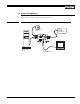
1.4 System Configuration
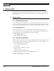
Figure 1 (below) presents a typical system configuration.
FIGURE 1.
TMC-7DSP/TMC-6DSP System Configuration
VIDEO
OPTION
AWB
SHUTTER
PWR/RGB
MODE
0
1
2
3
5
6
7
8
9
4
1
2
3
4
Power
Ext. Sync
Integration
Video Output*
Computer with
Frame Grabber
Board
* Video Output is the
same as BNC connector
Monitor
Auto-Iris Lens
(optional)