
Instruction manual


INSTALLATION
TMC-7DSP/TMC-6DSP Color CCD Camera Page 9
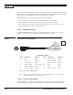
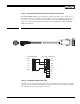
2.2.2 (f) RS-232C-9 Communication Cable and Connector (optional)
The TMC-7DSP/TMC-6DSP camera’s built-in microcomputer chip (CPU) can be controlled by an
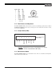
external RS-232C interface. The RS-232C-9 cable (Figure 5, “RS-232C-9 Cable”) connects to the 6-
pin connector on the rear of the camera. The internal CPU controls the TMC-7DSP/TMC-6DSP
camera’s operation mode and DSP parameter changes. Contact PULNiX for the TMC-7DSP/TMC-
6DSP software diskette.
FIGURE 5. RS-232C-9 Cable
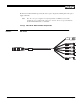
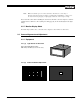
2.2.2 (g) Building Your Own Power Cable
Consult the pin-out for the camera purchased. Connect the Ground and +12V power leads of the PC-
12P power connector (Part #PC-12P) to Pin #1 and Pin #2, respectively (power must be DC regulated,
and of sufficient current to properly power the camera).
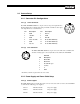
6-PIN CONNECTOR D-SUB 9-PIN CONNECTOR
RXD PIN 2 PIN 1 DCD
TXD PIN 2 PIN 2 RXD
+12V PIN 3 PIN 3 TXD
Y out PIN 4 PIN 4 DTR
C out PIN 5 PIN 5 GND
GND PIN 6 PIN 6 DSR
PIN 7 RTS
PIN 8 CTS
PIN 9 RI