
Instruction manual


INSTALLATION
Page 6 TMC-7DSP/TMC-6DSP Color CCD Camera
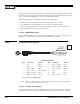
For users providing power through the 12-pin connector, the PD-12P power supply is available with the
12-pin mating connector already attached to the leads from the power supply. The PD-12 power supply
can be connected to the PULNiX power cable via a terminal strip or directly.
When wiring the PD-12 power supply directly, please note the following:
•
Twist the lead ends together and tin solder for strength and electrical continuity.
•
Use shrink tubing or a similar insulator to prevent exposed leads from touching.
•
The +12V lead is marked with a red stripe or white lettering; be sure not to reverse the leads.
•
Properly insulate all connections to prevent shorting.
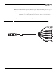
2.2.2 (b) PULNiX Power Cables
If you are using PULNiX power cables, such as the 12P-02, KC-10, etc., please refer to the pin-out
diagram. The color coded leads use Grey for Ground and Yellow for +12V DC.
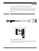
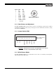
FIGURE 2.
12P-02 Interface Cable (optional)
* Not recommended for RGB Output
Note:
Make sure that the unused leads are not touching and that there is no possibility that
the leads could short due to exposed wires.
2.2.2 (c) “K” Series Power Supplies
Attach the 110V line cord to the two terminals marked “AC”. Do not plug the cord into a 110V AC
socket until later in the procedure. Next, attach the Grey and Yellow leads of the power cable to the
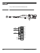
12P-02 Interface Cable
Pin# Lead Color Function Pin# Lead Color Function
1 Gray GND 7 Black coax signal Ext. Vd
2 Yellow +12VCD 8 White coax shield GND
3 Red coax shield GND 9 White coax signal Ext. Hd
4 Red coax signal Video out(VBS) 10 Brown R out*
5 Orange coax shield GND 11 Blue G out*
6 Orange coax signal Sync out 12 Black coax shield B out*
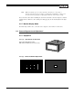
HD In (White Coax)
Video Out (Red Coax)
VD In (Black Coax)
Power (Yellow)
+12 V
GND (Gray)