
Instruction manual


INSTALLATION
TMC-7DSP/TMC-6DSP Color CCD Camera Page 5
2.2 Camera Setup
2.2.1 Connector Pin Configurations
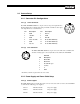
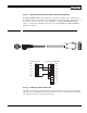
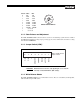
2.2.1 (a) 12-Pin Connector
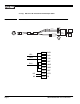
The TMC-7DSP/TMC-6DSP has a 12-pin connector for power input. Pin #1 is
Ground and Pin #2 is +12V DC. The other pins handle a number of other input
and output functions, as detailed below.
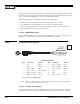
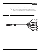
2.2.1 (b) 6-Pin Connector
The TMC-7DSP/TMC-6DSP has a 6-pin connector for RS-232C communication
and Y/C. A mating 6-pin connector (PC-6P) can be obtained from PULNiX.
* For Pin #3, 12V DC is optional for auto iris control.
2.2.2 Power Supply and Power Cable Setup
2.2.2 (a) Power Supplies
The TMC-7DSP requires 12 V DC. The 12pin connector is located at the rear of the camera. PULNiX
recommends the following power supplies:
K25-12 110V AC/12V DC 2.1A power supply
K50-12 110V AC/12V DC 4.2A power supply
PD-12P 110V AC/12V DC 0.5A power supply
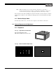
Pin Description Pin Description
1 GND 7 Ext. Vd
2 +12V DC 8 GND
3 GND 9 Ext. Hd
4 Video out (VBS) 10 R out (TMC-7DSP only)
5 GND 11 G out (TMC-7DSP only)
6 Sync out 12 B out (TMC-7DSP only)
Standard
Pin Description
1 RS-232 RX
2 RS-232 TX
3 NC (12V DC opt.)*
4 Y (video)
5C
6 GND
1
2
3
4
5
6
9
8
7
11
12
10
61
5
43
2