TMC-7DSP/TMC-6DSP Color CCD Camera Operation Manual September 10, 1999 69-0059 Rev.
Notice The material contained in this manual consists of information that is proprietary to PULNiX America, Inc., and may only be used by the purchasers of the product. PULNiX America, Inc. makes no warranty for the use of its product and assumes no responsibility for any errors which may appear or for damages resulting from the use of the information contained herein. PULNiX America, Inc. reserves the right to make changes without notice.
Table of Content 1 INTRODUCTION ..............................................................................................1 1.1 1.2 1.3 1.4 Product Description and Applications.................................................................................1 Features .............................................................................................................................1 Functional Options.............................................................................................
Table of Contents 4.2.11 Read Setting.........................................................................................................23 4.3 Troubleshooting and FAQ .................................................................................................24 4.3.1 Main Control Dialog Box Does Not Open ...............................................................24 4.3.2 Advanced Controls Are Not Operational ................................................................
List of Figures FIGURE 1. TMC-7DSP/TMC-6DSP System Configuration ..............................13 FIGURE 2. 12P-02 Interface Cable (optional)...................................................16 FIGURE 3. RS-232C Cable ..............................................................................17 FIGURE 4. Shutter Control Settings .................................................................21 FIGURE 5. TMCDSP Software Control Panel ..................................................
September 10, 1999 TMC-7DSP/TMC-6DSP Color CCD Camera Operation Manual 1 INTRODUCTION 1.1 Product Description and Applications The PULNiX TMC-7DSP/TMC-6DSP is a compact, high resolution color CCD camera offering the latest in high performance Digital Signal Process (DSP) technology. It is available in both NTSC (TMC7DSP) and PAL (TMC-6DSP) formats.
INTRODUCTION In addition to the standard VBS output, the TMC-7DSP/TMC-6DSP cameras feature separate outputs for the RGB signals with sync and Y/C output. RGB signals are output without the use of a “breakout” module. Separate RGB and sync signals can be output directly from the camera via the 12-pin connector. Y/C output is available via the 6-pin connector. The Y signal also can be used for auto iris control. • 1/60 to 1/10,000 sec.
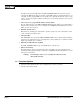
INTRODUCTION 1.4 System Configuration Figure 1 (below) presents a typical system configuration. FIGURE 1. TMC-7DSP/TMC-6DSP System Configuration Power Ext.
INSTALLATION 2 INSTALLATION The following instructions are provided to help you to set up your video camera system quickly and easily. It is suggested that you read through these instructions prior to unpacking and setting up your camera system 2.1 Getting Started 2.1.1 Unpacking Instructions It is recommended that the original packing cartons for the cameras and lenses be saved in case there is a need to return or exchange an item.
INSTALLATION 2.2 Camera Setup 2.2.1 Connector Pin Configurations 2.2.1 (a) 12-Pin Connector 1 The TMC-7DSP/TMC-6DSP has a 12-pin connector for power input. Pin #1 is Ground and Pin #2 is +12V DC. The other pins handle a number of other input and output functions, as detailed below. 2 3 Description Pin Description 1 GND 7 Ext. Vd 2 +12V DC 8 GND 3 GND 9 Ext. Hd 4 Video out (VBS) 10 R out (TMC-7DSP only) 5 GND 11 G out (TMC-7DSP only) 6 Sync out 12 B out (TMC-7DSP only) 2.2.
INSTALLATION For users providing power through the 12-pin connector, the PD-12P power supply is available with the 12-pin mating connector already attached to the leads from the power supply. The PD-12 power supply can be connected to the PULNiX power cable via a terminal strip or directly. When wiring the PD-12 power supply directly, please note the following: • Twist the lead ends together and tin solder for strength and electrical continuity.
INSTALLATION Ground and 12V DC terminals respectively. Be sure to replace the plastic terminal guard on the power supply at this time. Note: 2.2.2 (d) FIGURE 3. The “K” series power supplies are designed primarily for OEM users who will be mounting the power supply inside a protective enclosure. For use in exposed situations, the DC-12N and PD-12 are recommended. CBL-2R-7D RGB and Video Output Cable CBL-2R-7D RED GREEN BLUE SYNC C.
INSTALLATION 2.2.2 (e) FIGURE 4.
INSTALLATION 2.2.2 (f) RS-232C-9 Communication Cable and Connector (optional) The TMC-7DSP/TMC-6DSP camera’s built-in microcomputer chip (CPU) can be controlled by an external RS-232C interface. The RS-232C-9 cable (Figure 5, “RS-232C-9 Cable”) connects to the 6pin connector on the rear of the camera. The internal CPU controls the TMC-7DSP/TMC-6DSP camera’s operation mode and DSP parameter changes. Contact PULNiX for the TMC-7DSP/TMC6DSP software diskette. FIGURE 5. RS-232C-9 Cable 6-PIN CONNECTOR 2.
INSTALLATION 2.2.2 (h) Attaching the Power Cable to the Connector The 12-pin connector is keyed and will only fit in one orientation. Rotate the connector while applying slight pressure until the keyways line up. Press the connector into place until firmly seated. The power cord may now be plugged into the 110V AC socket, and the camera powered up. 2.2.3 Attaching the Video Output Most users utilize the BNC connector for video output from the camera.
INSTALLATION Note: Make sure that the power is removed from the camera before connecting or disconnecting the auto-iris lens. There is a small chance that damage could occur to the auto-iris lens by plugging or unplugging it while the camera is powered up. Power down the camera before installing the auto-iris lens. Point the camera at a light area and then quickly towards a darker area. If everything is working properly, the iris should adjust for the light change. 2.2.
OPERATION 2.3.1 (c) Color Bar Chart for Color Adjustment YL 2.3.1 (d) CY G W MG R B Signal Adjustment Vector Scope Waveform monitor Oscilloscope 3 OPERATION 3.1 Modes of Operation 3.1.1 Shutter Control Functions 3.1.1 (a) Electronic Shutter Control The capability to externally vary the electronic shutter rate from 1/60 sec. to 1/10,000 sec. is a standard feature of the TMC-7DSP/TMC-6DSP camera.
OPERATION NTCS PAL 1/60 1/50 1/100 1/120 1/250 1/250 1/500 1/500 1/1,000 1/1,000 1/2,000 1/2,000 1/4,000 1/4,000 1/10,000 1/10,000 (not used) (not used) 4 56 78 9 01 2 3 Switch 0 1 2 3 4 5 6 7 8 9 Shutter Control Switch 3.1.2 Color Balance and Adjustment The TMC-7DSP/TMC-6DSP cameras feature an advanced color balancing system which is controlled by DSP (Digital Signal Processing). Upon powering up, the camera will load the color balance setting from the internal EEPROM. 3.1.
OPERATION TABLE 1. White Balance Mode Selection Table Mode SW1 SW2 SW3 ATW Up (0) Up (0) Up (0) Push lock Up (0) DN (1) Up (0) Hold DN (1) DN (1) Up (0) Indoor fixed value Up (0) Up (0) DN (1) approx. 3200K Fluorescent light fixed value DN (1) Up (0) DN (1) approx. 4200K User (fl. light fixed value 2) Up (0) DN (1) DN (1) approx. 4700K Outdoor fixed value DN (1) DN (1) DN (1) approx. 6300K 3.1.4 (a) Set color temp.
OPERATION 3.1.4 (d) Automatic Exposure (AE) AE SW4 AE/ME JSW1 FLON JSW2 BLCOF JSW3 MIRIS JSW4 AEREF JSW5 AGCMAX UP (L) AE Mode Close (L) Flickerless OFF Close (L) Background lighting correction ON Close (L) Electronic iris Close (L) 1001RE setting Close (L) 20dBmax Open (H) *1 Flickerless ON Open (H) Background lighting Correction OFF Open (H) Mechanical iris Open (H) User setting values Open (H) 26dBmax DOWN ME Mode JSW1-4 are not active in ME mode *1.
OPERATION 3.1.5 Software Control Features Most of the TMC-7DSP/TMC-6DSP’s functions can be controlled by PC via RS-232C communication using TMCDSP, PULNiX’s proprietary software. Below is a summary of these functions. Detailed instructions for using the software program will be provided in Section 4, “SOFTWARE INSTRUCTIONS,” on page 18. For cable information see 2.2.2(f) on page 8. FIGURE 7.
OPERATION 3.2.1 Top Board FIGURE 8. TMC-7DSP/TMC-6DSP Top Board VR6 VR5 J2 VR4 J5 VR3 VR2 J1 SW1 12345678 SW1 1 2 3 4 5 6 7 8 Flon Blcof Miris Aeref AGCMAX Gamma Not used Not used VR2 VR3 VR4 VR5 VR6 APL Sharpness C-Gain Hue PLL 3.0± 0.1V 2.5± -/1V 1.8± 0.1V 3.2± 0.1V 3.2.2 Bottom Board FIGURE 9.
SOFTWARE INSTRUCTIONS 4 SOFTWARE INSTRUCTIONS The TMC-7DSP/TMC-6DSP camera can be operated from a PC using TMCDSP, PULNiX’s proprietary software program. Following are the instructions for installing and using the software. 4.1 Software Installation 4.1.
SOFTWARE INSTRUCTIONS 4.2 Operating the Control Interface 4.2.1 Before Running TMCDSP.EXE Before running TMCDSP.EXE, the video format (NTSC or PAL) and the serial communication port to be used for camera control must be customized. The procedure is as follows: 1. 2. 3. 4. 5. FIGURE 10. Go to the application directory (default is C:\ProgramFiles\pulnix\TMCDSP) and open camsetting.reg. Specify the comport number (ex: 1, 2 or 3) in the “camsetting.reg” file. If you are not sure, you may leave this blank.
SOFTWARE INSTRUCTIONS 4.2.2 Shutter Mode Control In Shutter Mode Control, you can specify either AE (Auto Exposure) or Manual shutter mode. 4.2.2 (a) Auto Exposure Mode In AE mode, the camera automatically sets the shutter speed and dynamically adjusts it according to the conditions of the light source. Note: 4.2.2 (b) Selecting AE mode enables Back Light Compensation control (see Section 4.2.5 on page 22), but disables shutter speed spin box.
SOFTWARE INSTRUCTIONS FIGURE 11. White Balance Control 4.2.3 (a) Internal White Balance Mode Selecting Internal White Balance mode enables auto white balance adjustment of the camera controlled internally by accumulators built-in DSP. The Complete Pull-in option (“Cmp Pl”) sets a threshold of color values to adjust white balance. For instance, if you want the camera to adjust white balance no matter what the colors, you may want to check this option.
SOFTWARE INSTRUCTIONS FIGURE 12. Setting Values in “User” External White Balance Mode 4.2.4 Gamma Control Gamma correction can be switched on and off by using the Gamma Control Select Combo box (right). 4.2.5 Back Light Compensation Control Back light compensation can be switched on or off by using the Back Light Compensation Select Combo box (right). Note that the back light compensation feature is only enabled when AE (auto exposure) shutter mode is selected. 4.2.
SOFTWARE INSTRUCTIONS 4.2.7 Aperture Control The default setting is Aperture Off. Switching on Aperture can enhance the edges of an image horizontally and vertically. Aperture ON/OFF is selected by choosing On or Off from the Aperture menu (right). 4.2.8 Y Gain Control Default Y Gain is set as 134 in decimals. To change this value, edit the value in the Edit box (right), either by sliding the Y Gain slider control or by clicking the large and small up/down arrow buttons.
SOFTWARE INSTRUCTIONS 4.2.10 (a) Writing the Current Setting onto the Hard Disk as a File TMCDSP allows you to save your current setting as a text file on your PC’s hard disk. From the menu bar, select “File” -> “Save As” (below). The current setting is saved in ASCII format. An example is shown below (Figure 13, “ASCII Text Format Example”). This text file can be modified or edited using any type of text editor tool. Character ‘#’ represents the start of a comment.
SOFTWARE INSTRUCTIONS 4.2.10 (b) Writing the Current Setting to EEPROM The current setting can also be saved by writing the setting to EEPROM. Select “Write” -> “EEPROM” from the menu bar (below). The following parameters are not loaded from EEPROM upon booting up. At boot time, the back panel mode switch controls these parameters.
TROUBLESHOOTING 4.3 Troubleshooting and FAQ Following are some troubleshooting suggestions for some common problems. If these suggestions do not solve your problem, please contact PULNiX (See “Information and Support Resources” on page 27.). 4.3.1 Main Control Dialog Box Does Not Open If the Main Dialog Box does not open, check the following: • Make sure that you have followed the correct installation procedure. • Check that you have correctly customized the “camsetting.
TROUBLESHOOTING 5.1.2 Symptom: Dark Video Remedies: Check that the following are properly connected and operational. • Shutter selection • Iris opening on the lens 5.1.3 Symptom: Non-synchronized Video Remedies: Check that the following are properly connected and operational. 5.
APPENDIX 6 APPENDIX 6.1 Specifications 6.1.1 Product Specifications TABLE 2. TMC-7DSP/TMC-6DSP Product Specifications Table Model Imager Pixels Cell size Color filter Scanning TMC-7DSP (NTSC) TMC-6DSP (PAL) 1/2" interline transfer CCD (6.4 x 4.8mm) 768 (H) x 494 (V) 752 (H) x 582 (V) 8.4µm (H) x 9.8µm (V) 8.6µm x 8.3µm Cy, Ye, Mg, G complementary color filter 2:1 interlace, field mode scanning 525 lines, 59.94Hz Sync TV resolution S/N Ratio Min.
APPENDIX 6.1.2 Physical Dimensions Physical Dimensions FIGURE 14. 42 mm 118 mm (Remote) PULNiX 32 mm 133mm 146mm PULNiX 29 mm 25 mm 25 mm 50mm 35 mm 1/4 - 20 UNC -2B 48 mm M2.6 x 7mm.
APPENDIX 6.1.3 Glass Specifications FIGURE 15. Camera Front End - Glass Specifications CCD Glass (BK-7) 0.75mm thickness Refractive Index = 1.5 Glass Cover (BD-65) 1.0mm thickness Refractive Index = 1.51 CCD Glass Cover CCD Glass 6.1.4 C-Mount Specifications FIGURE 16. C-Mount The Flange Back Length of the CS-Mount is 12.5mm versus 17.526 of the C-Mount. The shorter Flange Back Length of the “CS-Mount” allows room for the stripe filter incorporated in the color camera.
APPENDIX FIGURE 17. Combination With “CS-Mount” Camera Focal Point 5mm Extension Ring C-Mount Lens 5 12.5 17.526 Flange Surface of C-Mount 6.1.5 Front End Detail FIGURE 18.
APPENDIX 6.2 Imager Color Filters 6.2.1 Spectral Response with Complementary Mosaic Filter FIGURE 19. Spectral Response 1.0 .9 Relative Response .8 Ye .7 Cy .6 G .5 .4 Mg .3 .2 .1 .0 400 500 600 700 Wavelength (nm) 6.2.2 Complementary Stripe Filter FIGURE 20.
APPENDIX 6.3 Timing Chart HD 6.7µSec 818 768 B45 45 757 758 759 760 761 762 763 764 765 766 767 768 5 B1 B2 B3 B4 B5 1 2 3 4 5 6 7 8 9 10 D1 22 D22 70 B45 B1 763 764 765 766 767 768 45 B1 96 6 CCE photo sensors allocation Optical black period H register stop period 69.8nSec Image sensing period Dummy H register Optical black period CCD output signal Effective picture period 154 H BLK 10.7µSec Composite video output 22 1.54µSec 68 H SYNC 4.75µSec 64 4.47µSec 910 63.56µSec 756 52.
APPENDIX Page 34 TMC-7DSP/TMC-6DSP Color CCD Camera
Industrial Products Division PULNiX America, Inc. 1330 Orleans Drive Sunnyvale, CA 94089 Tel: 408-747-0300 Tel: 800-445-5444 Fax: 408-747-0660 Email: imaging@jaipulnix.com www.pulnix.