TMC-6700/1000 Series Progressive Scan CCD Digital Color Camera Operation Manual 69-0117 Rev.
Page i Notice Page Notice The material contained in this manual consists of information that is proprietary to PULNiX America, Inc., and may only be used by the purchasers of the product. PULNiX America, Inc. makes no warranty for the use of its product and assumes no responsibility for any errors which may appear or for damages resulting from the use of the information contained herein. PULNiX America, Inc. reserves the right to make changes without notice.
Page ii Table of Contents 1 Introduction . . . . . . . . . . . . . . . . . . . . . . . . . . . . . . . . 1 1.1 1.2 1.3 1.4 Product Description and Applications . . . . . . . . . . . . . . . Features . . . . . . . . . . . . . . . . . . . . . . . . . . . . . . . . . . . . . Functional Options. . . . . . . . . . . . . . . . . . . . . . . . . . . . . . System Configuration . . . . . . . . . . . . . . . . . . . . . . . . . . . 1 1 3 4 2 Installation . . . . . . . . . . . . . . . . . . . . . . . . . . . . . .
Page iii Table of Contents 4.2.5 Write 1 Byte Into RAM Bank . . . . . . . . . . . . . . . . . . . . . . . . . . 24 4.2.6 Read 1 Byte From RAM Bank . . . . . . . . . . . . . . . . . . . . . . . . . 25 4.3 Camera Control . . . . . . . . . . . . . . . . . . . . . . . . . . . . . . . .25 4.3.1 VCA Gain . . . . . . . . . . . . . . . . . . . . . . . . . . . . . . . . . . . . . . . . . 25 4.3.2 ADC Offset . . . . . . . . . . . . . . . . . . . . . . . . . . . . . . . . . . . . . . . . 26 4.3.3 ADC Ref. Top . . . .
Page iv List of Figures FIGURE 1. TMC-6700/1000 (Base models only) Series System Configuration . .4 FIGURE 2. TMC-6700CL/1000CL (Camera Link models only) Series System Configuration . . . . . . . . . . . . . . . . . . . . . . . . . . . . . . .4 FIGURE 3. 12P-02S Interface Cable (optional) . . . . . . . . . . . . . . . . . . . . . . . . .10 FIGURE 4. CBL-RS232-9 Cable. . . . . . . . . . . . . . . . . . . . . . . . . . . . . . . . . . . . . 11 FIGURE 5.
Page v List of Tables TABLE 1. 15-Pin SVGA Output Connector Configuration . . . . . . . . . . . . . . . . . 8 TABLE 2. 6-Pin Connector Pinout Configuration . . . . . . . . . . . . . . . . . . . . . . . . 8 TABLE 3. 26-Pin CL Connector Pinout Configuration . . . . . . . . . . . . . . . . . . . . 8 TABLE 4. Shutter Speed Control Settings (Factory Default) . . . . . . . . . . . . . . 15 TABLE 5. Camera Rear Panel Switches . . . . . . . . . . . . . . . . . . . . . . . . . . . . . 16 TABLE 6.
August 14, 2003 TMC-6700/1000 Series Progressive Scan CCD Digital Color Camera Operation Manual Models: TMC-1000, TMC-1000CL, TMC-6700, TMC-6700CL 1 Introduction 1.1 Product Description and Applications The TMC-6700/1000 series* cameras are digital process and output color video cameras which use a 1"(TMC-1000) and 1/2" (TMC-6700) high-resolution progressive scan interline transfer CCD.
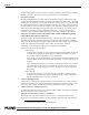
Page 2 Introduction The built-in Digital Signal Processor (DSP) is controlled via RS-232C communication for remotely adjusting color matrix, white balance, gain, edge enhancement, and other functions. • Progressive Scanning The TMC-6700/1000 series uses a state-of-the-art progressive scanning interline transfer CCD, which scans all lines sequentially from top to bottom at one frame rate (15Hz in TMC-1000, 60Hz in TMC-6700).
Page 3 Introduction TMC-6700) per shutter or integration. The user can assign any shutter speed to any of the preset shutter positions. • Asynchronous reset and shutter The TMC-6700/1000 series cameras asynchronous reset operates with internal sync or external HD for phase locking. There are three modes to control the asynchronous reset and shutter speed. • Integration The CCD imager of the TMC-6700/1000 series can be exposed for longer than one frame duration (1/15 sec. TMC-1000; 1/60 sec. TMC-6700).
Page 4 Introduction 1.4 System Configuration Figure 1(below) presents a typical system configuration for the base model. FIGURE 1. TMC-6700/1000 (Base models only) Series System Configuration 15CL-02 or 15CL-02-15 MAN ASY SHUTTER 78 IWB G1.0 BANK1 EWB 0.
Page 5 Introduction • Power supply Use the optional PD-series power supply or use cable 12P-02S (optional) that connects to the camera’s 12-pin Hirose connectors on one end and has flying heads for power and sync signals on the other end. • Display monitor Use cable CBL-2R-15 (optional) or a 15-pin SVGA cable to connect to an SVGA color monitor.
Page 6 Installation 2 Installation The following instructions are provided to help you to set up your video camera system quickly and easily. We suggest that you read through these instructions prior to unpacking and setting up your camera system. 2.1 Getting Started 2.1.1 Unpacking Instructions We recommend that you save the original packing cartons for the cameras and lenses in case you need to return or exchange an item.
Page 7 Installation 2.2 Camera Setup 2.2.1 Connector Pin Configurations 2.2.1 (a) 12-Pin Connector 1 The TMC-6700/1000 series has a 12-pin connector (PC-12P) on the rear panel for power input and integration control. 2.2.
Page 8 Installation 2.2.1 (c) 15-pin SVGA Output Connector (base only) pin 1 The analog RGB output connector is a high-density D-Sub 15-pin connector. TABLE 1. pin 6 15-Pin SVGA Output Connector Configuration pin 11 2.2.
Page 9 Installation TABLE 3. 26-Pin CL Connector Pinout Configuration (Continued) Camera Link Connector MDR 26-Pin Connector 10226-6212VC Pin # Description I/O Pin # Description I/O 5 Tx CLK OUT - Out 18 Tx CLK OUT + Out 6 Tx OUT 3 - Out 19 Tx OUT 3+ Out 7 SerTC+ In 20 SerTC - In 8 SerTFG- Out 21 SerTFG+ Out 9 VINIT - (CC1-) In 22 VINIT + (CC1+) In 10 INTEG + (CC2+) In 23 INTEG- (CC2-) In 11 N/C 24 N/C 12 N/C 25 N/C 13 GND 26 GND 2.2.
Page 10 Installation 2.2.2 (b) PULNiX Power Cables If you are using PULNiX power cables, such as the 12P-02S, please refer to the12-pin connector pin-out diagram in Section 2.2.1 on page 7. The cable pin-out diagram is shown below in Figure 3. The colorcoded leads use Gray for Ground and Yellow for +12V DC.
Page 11 Installation 2.2.3 RS-232C Cosmmunication Cable and Connector FIGURE 4. CBL-RS232-9 Cable 6 1 5 1 6 5 9 2 4 3 2,000.0mm ±25mm (2 meters) The RS-232 controller set CS-232C includes CBL-RS232-9 interface cable, software diskette, and a quick-start card. The TMC-6700/1000 series camera’s built-in DSP chip can be controlled by an external RS-232C interface. The camera settings can be programmed or changed using the communication cable and software.
Page 12 Installation 2.2.5 Analog Output Cable (CBL-2R-15) FIGURE 6. Analog Output Cable (CBL-2R-15) 6 FEET REF. (1.83 METERS) 6 INCHES (REF.) (15.9 CM) RED HDB15 MALE HIGH DENSITY D-SUB CONNECTOR GREEN PIN 1 BNC PLUGS (5) BLUE PIN 14 BLACK AY V GR OR W HI TE VERT. SYNC 1 H HORIZ. SYNC The RGB analog cable has a 15-pin high-density D-sub connector on the camera end, and five BNC connectors on the frame-grabber end.
Page 13 Installation 2.2.7 Back-Focusing the Lens Follow these directions to back-focus the TMC6700/1000 series camera. 1. Attach a C-mount lens to the camera. Be sure that the lens is properly mounted. 2. Loosen the three miniature set screws holding the focus ring. 3. Set the lens focus to infinity. 4. Point the camera at a distant object and turn the focus ring to obtain the best possible focus. 5. Set Screws (quantity 3) Lens Back-Focus Ring Tighten the focus-ring set screws.
Page 14 Operation Operation 3.1 Camera Rear Panel-Base Only FIGURE 7. TMC-6700/1000 Series Rear Panel White Balance Reset IWB RST (3) Shutter Mode Switch (2) White Balance Control (4) Gamma Control Switch (5) MAN ASY IWB RST 78 9 01 Bank Switch (6) 2 34 Shutter Dial (1) IWB G1.0 BANK1 EWB 0.45 BANK2 SHUTTER 56 POWER DIGITAL RS-232 (7) RS 232 Power (10) Analog (8) ANALOG Digital (9) 3.1.
Page 15 Operation Note: TABLE 4. In order to avoid video problems, make sure that you turn the shutter-speed control dial quickly. If you turn the dial too slowly, the shutter may not expose for the proper period of time, resulting in either no video or bright video. If this happens, push the IWB RST switch on the rear panel or repeat the dial change at a faster speed.
Page 16 Operation 3.2 Camera Rear Panel Switches and Connectors The following two charts list and describe the features of the camera rear panel illustrated in Figure 7. Table 5 on page 16 contains information on the switches on the rear panel and Table 6 on page 17 contains information on connectors on the rear panel. TABLE 5.
Page 17 Operation TABLE 6. Camera Rear Panel Connectors # Connector Type Cable Needed Cable Information 7 RS-232 6-pin female connector CBL-RS232-C9 Connect PC to the camera using the RS-232C control cable (CBLRS232-C9). This cable is a part of the communication kit (CS-232C). 8 Analog 15-pin High Density D-sub female connector CBL-2R-15 If you are using a monitor or frame grabber that needs Red, Green, Blue, Vertical Sync, and Horizontal Sync, then use the RGB analog cable (CBL-2R-15).
Page 18 Operation The mathematical transformation is a linear-space 3 x 3 matrix operation, as shown below. 1.75 – 0.25 – 0.5 Ri Ro Go = – 0.1875 1.3125 – 0.125 Gi – 0.125 – 0.5 – 1.625 Bi Bo The coefficients have been optimized for the spectral sensitivities of a Bayer CFA (color filter array). For camera systems, a linear-space color correction matrix is used. The coefficients are programmable through the serial interface. 3.3.4 User-Programmable Functions 3.3.
Page 19 Operation RAM banks can be saved by the EEPROM save command (Section 4.2.3, “Save RAM Data Into EEPROM,” on page 24). 3.3.4 (f) Black Level Control The TMC-6700/1000’s DSP has independent red, green and blue offset controls, and black level control. The user can calibrate these under specific lighting conditions by using the RS-232 control. 3.3.4 (g) RS-232 External Communication The TMC-6700/1000 series is capable of being controlled by external communication via RS-232.
Page 20 Operation FIGURE 9. Asynchronous Reset ASYNC RESET VINIT VD SG (TRANSFER GATE) DISCHARGE PULSES VIDEO Async Image Stand-by Image 3.5.2 Asynchronous Reset and Shutter Speed The TMC-6700/1000 series asynchronous reset operates with internal sync or external HD for phase locking. When VINIT pulse is applied, it resets the camera’s scanning and purges the CCD.
Page 21 Operation FIGURE 10. External Pulse Width Control External Pulse Width X (min. 1H) Hd Internal Vinit 9H Transfer Gate Pulse 18H Exposure Time Discharge pulse Composite Video 3.5.2 (b) Long Integration With pulse-width control, long integration is possible up to a few seconds besides integration control (pin #11 of the 12-pin connector). 3.5.
Page 22 TMC-6700/1000 Series RS-232C Control 4 TMC-6700/1000 Series RS-232C Control* 4.1 RS-232C Control Introduction The TMC-1000’s DSP parameters and operation mode can be controlled by an external RS-232C interface. The camera features four memory banks that store camera configuration parameters such as shutter speed, color matrix, white balance, gain, and edge enhancement. The first two banks, Bank1 and Bank2, can be selected via the Bank Switch on the back panel of the camera.
Page 23 TMC-6700/1000 Series RS-232C Control 4.2 Basic Command Code 4.2.1 Set/Refresh RAM Bank Function: Set or refresh the RAM bank. Four user’s RAM banks are available from Bank 1 to Bank 4. Typical situations in which you may want to use this command are when you want to change to another RAM bank, and when you want to reflect changes after sending the shutter command, WB command, etc.
Page 24 TMC-6700/1000 Series RS-232C Control D3 D2:0 Rear Panel Override Flag Ram Bank Number -1 (0, 1, 2 or 3) D3 is the rear panel override flag, indicating whether the software or the rear panel has priority regarding parameter control. Note: Once any rear panel switch is changed, rear panel control will take priority, and the configuration of all the rear panel switch settings will apply to the current image: 4.2.3 Save RAM Data Into EEPROM Function: Save all four RAM data banks into EEPROM.
Page 25 TMC-6700/1000 Series RS-232C Control D0 D1 D7:0 D2 D3 D4 D5 D6 D7 8-bit data to update The first command code specifies the RAM address to write. The RAM address is shown in the Appendix, Section 6.3, “TMC-6700/1000 Series Control Parameter Address Map,” on page 36. The second command code specifies the new 8-bit data to overwrite. 4.2.6 Read 1 Byte From RAM Bank Function: Read 1 byte of data from the location of a specific address in the RAM bank.
Page 26 TMC-6700/1000 Series RS-232C Control *Note: The byte order of the ADC offset, VCA gain and ADC Ref. Top is opposite to that which is actually seen. For instance, if the user needs to write 48 (00110000 in binary code) as the new VCA gain, the code for 48 must be sent (00001100). Note: The particular RAM bank may be set prior to write or read. The image will not be updated until you set (refresh) the RAM bank after the write or read operation. 4.3.
Page 27 TMC-6700/1000 Series RS-232C Control 4.3.4 White Balance The white balance mode is saved in address 6 in RAM. If the internal WB mode is set, then the TMC6700/1000 series internally accumulates R and B white balance. If the external WB mode is set, then the external WB-R and WB-B offset are loaded from address 2B (hex) and 2A (hex) respectively. WBR and WB-B offsets can be updated by accessing addresses 2B and 2A (hex). WB-R and WB-B in these addresses are 2’s complement representation.
Page 28 TMC-6700/1000 Series RS-232C Control Set V Enh and level 3 (RGB, Int. WB) Tx1 01000110 (address 6, write) Tx2 00111000 Tx3 Refresh RAM Bank 4.3.6 RGB to YCrCb Conversion RGB to YCrCb Conversion mode is saved in address 6. The TMC-6700/1000 series supports RGB, 4:4:4 YCrCb and 4:2:2 YCrCb. Please refer to Section 4.3.4, “White Balance,” on page 27. Example Set 4:2:2 YCrCb (Edge Enh Bypass, Int. WB) Tx1 01000110 (address 6, write) Tx2 10000000 Tx3 Refresh RAM Bank 4.3.
Page 29 TMC-6700/1000 Series RS-232C Control n-1 when n is exposing line count.
Page 30 TMC-6700/1000 Series RS-232C Control Tx6 Tx7 Tx8 Tx9 Tx10 Tx11 Tx12 Tx13 Tx14 Tx15 Tx16 Tx17 Tx18 Tx19 11111100 01100001 (Address of GB) 11111100 01100010 (Address of GG) 00101010 01100011 (Address of GR) 11111010 01100100 (Address of RB) 11110000 01100101 (Address of RG) 11111000 01100110 (Address of RR) 00111000 Refresh RAM Bank 4.3.
Page 31 Troubleshooting 5 Troubleshooting 5.1 Problems and Solutions Following are troubleshooting tips for common problems. In general, problems can easily be solved by following these instructions. If the following remedies fail to offer a solution to your problems, please contact a PULNiX representative. 5.1.1 Symptom: No Video Remedies: Check that the following are properly operational.
Page 32 Troubleshooting 5.2 Information and Support Resources For further information and support: Phone: (408) 747-0300 (800) 445-5444 (800) 3-PULNIX (24-hour message access) Fax: (408) 747-0660 E-mail: imaging@jaipulnix.com Mail: PULNiX America, Inc. Sales Department 1330 Orleans Drive Sunnyvale, CA 94089 ATTN: Video Applications Web Site: www.pulnix.
Page 33 Appendix 6 Appendix 6.1 Specifications 6.1.1 Product Specifications TABLE 7. TMC-6700/1000 Series Product Specifications Table TMC-1000/1000CL TMC-6700/6700CL Imager 1” progressive scanning interline transfer CCD 1/2” progressive scanning interline transfer CCD Pixels 1008 (H) x 1018 (V) 648 (H) x 484 (V) Cell size 9.0µm x 9.
Page 34 Appendix 6.1.2 Physical Dimensions FIGURE 11. TMC-6700/1000 Series Physical Dimensions 116.5 (4.58) 67.0 (2.64) 112.5 (4.43) PULNiX PROGRESSIVE SCAN 51.0 (2.01) 7.0 (.28) 11.0 1/4"-20 11.0 2XM6 2x ø5/50 22.0 CL 11.5 40.
Page 35 Appendix 6.2 Imager Color Filters 6.2.1 Spectral Response with Complementary Mosaic Filter FIGURE 12. Spectral Response (RGB PRIMARY COLOR FILTER) 1.0 GREEN 0.9 RED Relative S ensitivity 0.8 BLUE 0.7 0.6 0.5 0.4 0.3 0.2 0.1 0 300 400 500 600 700 800 900 1000 1100 Wave Length (nm) 6.2.2 Bayer Primary Color Filter FIGURE 13.
Page 36 Appendix 6.3 TMC-6700/1000 Series Control Parameter Address Map FPGA RAM Dec Addr. Hex Addr.
Page 37 Appendix 6.4 Digital Output Wave Forms FIGURE 14. Line Data Valid (TMC-1000/1000CL) 0 HD 128N 1N = 49.91 nsec 25.5N LDV H-SYNC 52.5N 50N 206N 42.5N 10N DATA 266N 1006N (active data) 1272N FIGURE 15. Frame Data Valid (TMC-1000/1000CL) VD 1H 1H = 1272N 3H FDV V-SYNC 2H DATA 2H 43H 1016H (active data) FIGURE 16. Line Data Valid (TMC-6700/6700CL) 0 HD 105N 2.5N 52.5N LDV H-SYNC 1N = 39.23 nsec 50N 154N 42.
Page 38 Appendix FIGURE 17.
Imaging Products www.pulnix.com PULNiX America, Inc. 1330 Orleans Drive Sunnyvale, CA 94089 Tel: 408-747-0300 Tel: 800-445-5444 Fax: 408-747-0660 Email: imaging@jaipulnix.com 69-0117 Rev.