TM-4000CL Series Progressive Scan Shutter Cameras Operation Manual 69-0116 Rev.
i Notice Page Notice The material contained in this manual consists of information that is proprietary to JAI PULNiX, Inc., and may only be used by the purchasers of the product. JAI PULNiX, Inc. makes no warranty for the use of its product and assumes no responsibility for any errors which may appear or for damages resulting from the use of the information contained herein. JAI PULNiX, Inc. reserves the right to make changes without notice.
Page ii Table of Contents 1 Introduction . . . . . . . . . . . . . . . . . . . . . . . . . . . . . . . . . . . . . . . 1 2 Installation . . . . . . . . . . . . . . . . . . . . . . . . . . . . . . . . . . . . . . . . 4 1.1 1.2 1.3 2.1 Product Description . . . . . . . . . . . . . . . . . . . . . . . . . . . . . . . . . . . 1 Features . . . . . . . . . . . . . . . . . . . . . . . . . . . . . . . . . . . . . . . . . . . . 2 System Configuration . . . . . . . . . . . . . . . . . . . . . . . . . . . . . .
Page iii Table of Contents TM-4000CL Series Progressive Scan Shutter Cameras
Page iv List of Figures FIGURE 1. CL (Camera Link) System Configuration . . . . . . . . . . . . . . . . . . . . . . . . . . . . 3 FIGURE 2. 3M Camera Link Cable. . . . . . . . . . . . . . . . . . . . . . . . . . . . . . . . . . . . . . . . . . 6 FIGURE 3. 12P-02S Interface Cable (optional) . . . . . . . . . . . . . . . . . . . . . . . . . . . . . . . . 8 FIGURE 4. Internal Shutter Speed Control (TM-4000CL). . . . . . . . . . . . . . . . . . . . . . . . 12 FIGURE 5. No-Delay Shutter . . . . . . . .
Page v List of Tables TABLE 1. 12-Pin Connector . . . . . . . . . . . . . . . . . . . . . . . . . . . . . . . . . . . . 5 TABLE 2. Connector and Pin-out Configurations . . . . . . . . . . . . . . . . . . . . 5 TABLE 3. TM-4000CL Preliminary Command List . . . . . . . . . . . . . . . . . . 25 TABLE 4. TM-4000CL Camera Specifications Table . . . . . . . . . . . . . . . .
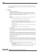
January 12, 2004 TM-4000CL Series Progressive Scan Shutter Cameras Operation Manual 1 Introduction 1.1 Product Description The PULNiX TM-4000CL series1 consists of dual-tap output, high-resolution, high-speed monochrome progressive scan CCD cameras. 2The interline-type CCD permits full vertical and horizontal resolution of very high speed shutter images and applications. The electronic shutter, which has speeds to 1/16,000 sec., can be reset asynchronously by external pulse control.
Page 2 Introduction Applications for the TM-4000CL include machine vision, medical imaging, intelligent transportation systems, high-definition graphics, on-line inspection, gauging, character reading, archiving, and highsecurity surveillance. 1.2 Features • Miniaturized and lightweight The printed circuit boards in the TM-4000CL have been arranged based on a new design philosophy. This creates modular electronics for the camera, giving it flexibility.
Page 3 Introduction • Output The TM-4000CL has a dual tap 10-bit or 8-bit Camera Link output. The analog output is 714 mVp-p composite video (75 ohms) on all models. • Dual-Channel Auto Black Level Balancing and Auto Gain The TM-4000CL, as a dual-tap output camera, has dual-channel auto black level balancing and auto gain balancing functions. • Integration The TM-4000CL is capable of capturing high-resolution integration images.
Page 4 Installation 2 Installation The following instructions are provided to help you to set up your camera quickly and easily. We suggest that you read through these instructions before you unpack and set up your camera system. 2.1 Getting Started 2.1.1 Unpacking Instructions We recommend that you save the original packing cartons for the cameras and accessories in case you need to return or exchange an item.
Page 5 Installation • Mount the camera on a large heat sink (camera bracket) made out of heat-conductive material like aluminum. • Make sure the flow of heat from the camera case to the bracket is not blocked by a non-conductive material like plastic. • Make sure the camera has enough open space around it to facilitate the free flow of air. Please contact JAI PULNiX, Inc. at (800) 445-5444 or send an E-mail to imaging@jaipulnix.com if you have any questions. 2.2.2 Connector Pin Configurations 2.2.
Page 6 Installation Camera Link Connector (Continued) Pin # Description 3 Tx OUT 1- 4 Pin # Description I/O Out 16 Tx OUT 1+ Out Tx OUT 2- Out 17 Tx OUT 2+ Out 5 Tx CLK OUT - Out 18 Tx CLK OUT+ Out 6 Tx OUT 3- Out 19 Tx OUT 3+ Out 7 SerTC+ In 20 SerTC- In 8 SerTFG- Out 21 SerTFG+ Out 9 VINIT- /CC1- In 22 VINIT+ In/CC1+ 10 INTEG+/CC2+ In 23 INTEG- In/CC2- 11 EX-HD-/CC3- In 24 EX-HD+ In/CC3+ 12 EX-VD+/CC4+ In 25 EX-VD- In/CC4- 13 GND 26 GND
Page 7 Installation 2.2.4 Power Supplies and Power Cable Setup 2.2.4 (a) Power Supplies The TM-4000CL camera requires 12V DC power that is obtained through the 12-pin connector located on the rear panel of the camera. PULNiX recommends the following power supplies: PD-12UU 100-240V AC/12V DC 1.
Page 8 Installation 12P-02S Interface Cable (optional) FIGURE 3.
Page 9 Installation The multi-conductor cable 12P-02S from PULNiX can be used to transmit analog video, power, sync. signals, and serial communication. The mini coaxial leads in PULNiX multi-conductor cables are designed for short runs of no longer than 50 feet. Note: Make sure that no extraneous wires are visible which could cause a short. 2.2.6 Attaching the Camera Lens The TM-4000CL camera accepts 1.2" or larger format size C-mount lenses.
Page 10 Operation 3 Operation 3.1 Camera Rear Panel CAMERA LINK 1 2 3 9 11 4 8 10 7 12 5 6 POWER 3.1.1 VIDEO Digital I/O Connector (Camera Link) Refer to Section 2.2.3 on page 6 for information on digital output connectors. 3.1.2 Analog Output Connector The camera has a BNC connector on the rear panel to output analog video signal. 3.1.3 Power and External Sync Connector Refer to Section 2.2.2 (b on page 5 for information on the power and external sync. connectors. 3.
Page 11 Operation The TM-4000CL outputs the progressive-scanned image with an electronic shutter in two different formats: 1. Progressive-scanning digital and analog output The CCD signal goes through A/D and D/A converters and through 10-bit in, 10-bit or 8bit out look-up table (LUT). The analog output is the same as 75 ohms, 714mVp-p format available from BNC and 12-pin connector. The digital output is available via the Camera Link connector. 2.
Page 12 Operation 3.5 Asynchronous Reset ASYNC RESET VINIT VD SG (TRANSFER GATE) DISCHARGE PULSE FDV PROGRESSIVE OUTPUT VIDEO Stand-by Image Stand-by Image Shutter Video The TM-4000CL camera includes two modes to control the asynchronous reset and shutter speed: • Internal Shutter Speed Control • External VINIT with Pulse Width 3.5.1 Internal Shutter Speed Control (TM-4000CL) EXT. VINIT HD INT.
Page 13 Operation 3.5.2 External VINIT With Pulse Width No-Delay Shutter and ROI (Read-out Inhibit) (TM-4000CL) For multiple-camera applications such as 2D or 3D measurement and multi-angle inspection, simultaneous image capturing at an exact shutter timing for all cameras is a critical requirement. The TM-4000CL’s asynchronous pulse-width control mode provides no-delay shutter as standard.
Page 14 Operation FIGURE 5. No-Delay Shutter and Read-Out Inhibit VINIT (External Pulse Width Control Trigger) No-Delay Shutter (All cameras) Discharge No-delay Exposure Transfer Gate ROI pulse width: Min. 1H to 1frame ROI Control: Camera #1 Camera #1 Video FDV/Vsync Max. 1H delay ROI Control: Camera #2 Camera #2 Video 3.6 Dynamic Range Control Blooming adj. = 13. 5 V Lens: F=5.6 mV Vsub = 8 V Max.
Page 15 Operation A typical CCD camera does not use the full dynamic range due to the nominal gain and the output specification such as RS-170. The typical CCD camera’s gain is set at 16 to 22 dB and the RS-170 video level is 714 mV. Using 20 dB gain for the calculation, CCD output is limited to 714/10 = 71.4 mV. Since the CCD’s saturation voltage is 400 mV to 500 mV, it uses less than 1/5 of the full dynamic range.
Page 16 Operation top to bottom and, unique in an interlace-scan camera, all lines are obtained per image capturing with electronic shutter. 3.7.2 Partial Scan TM-4000CL has centered 1000 lines, 500 lines and 250 lines partial scan mode.
Page 17 Operation 3.8 External Sync and Pixel Locking The TM-4000CL accepts an external sync of standard HD and VD at TTL level for general locking to a system sync and clock.The frequency requirement is as follows: Full Progressive Scan: fHD = 30.769 KHz ± 2% fVD = 14.79 Hz ± 2% (Internal Master clock = 80.00 MHz, Pixel clock = 40.00 MHz) 100L Partial Scan: fHD = 30.769 KHz ± 2% fVD = 27.97 Hz ± 2% 500L Partial Scan: fHD = 30.769 KHz ± 2% fVD = 49.63 Hz ± 2% 250L Partial Scan: fHD = 30.
Page 18 Operation 3.9 Camera Timing Charts Model: TM-4000 Operation Mode: Dual Tap Output Master Clock: 80.000 MHz, M=12.5 nsec Pixel Clock: 40.000 MHz, P= 25.0 nsec 1. Pixel Clock and Digital Data Pixel Clock A Data Tcd Tdc Thd Tcd: Clock to Data Ready Tdc: Data Ready to Next Clock Thd: Data Hold Time Tcd = 12.5 nsec, Tdc = 12.5 nsec, Thd = 7 nsec. 2. Horizontal Signals Timing fHD = [ 30.78 KHz] tHD = [ 32.5 µsec] External HD A [ 100 P],( 2.50 µs) Internal HD B [ 1200 P], ( 30.
Page 19 Operation Model: TM-4000 Master Clock: 80.000 MHz, M= 12.5 nsec Pixel Clock: 40.000 MHz, P= 25.0 nsec Operation Mode: Dual Tap Output Full Scan 14.79 Frames/second 3. External Reset Timing and Vertical Signals Timing External VD A [ 2080 H], (67.6 msec) B [ <1 H], ( <32.5 µs) Internal VD C [ 9 H], (0.29 ms) D [ 2071 H], ( 67.3 ms) E [ 2080 H], ( 67.6 ms) G [ 32 H], ( 1.04 ms) FDV H [ 2048 H], ( 66.56 ms) F [ 0 H], ( 0.0 µs) J [ 32 H], ( 1.04 ms) Digital Data K [ 2048 H], ( 66.
Page 20 Operation Model: TM-4000 Master Clock: 80.000 MHz, M= 12.5 nsec Pixel Clock: 40.000 MHz, P= 25.0 nsec Operation Mode: Dual Tap Output Centered 1000Ls PS 27.97 Frames/second 5. External Reset Timing and Vertical Signals Timing External VD A [ 1100 H], ( 35.75 msec) C [ 9 H], (0.29 ms) B [ <1 H], ( <32.5 µs) Internal VD D [ 1091 H], ( 35.4575 ms) E [ 1100 H], ( 35.75 ms) G [ 100H], ( 3.25 ms) FDV F [ 0 H], ( 0.0 µs) H [ 1000 H], ( 32.5 ms) J [ 100H], ( 3.25 ms) Digital Data I [ 0 H], ( 0.
Page 21 Operation Model: TM-4000 Operation Mode: Master Clock: 80.000 MHz, M= 12.5 nsec Pixel Clock: 40.000 MHz, P= 25.0 nsec Dual-Tap Output Centered 500Ls PS 49.63 Frames/second 7. External Reset Timing and Vertical Signals Timing External VD A [ 620 H], ( 20.15 msec) C [ 9 H], (0.29 ms) B [ <1 H], ( <32.5 µs) Internal VD D [ 611 H], ( 19.8575 ms) E [ 620 H], ( 20.15 ms) G [ 120H], ( 3.90 ms) FDV F [ 1 H], ( 32.5 µs) H [ 500 H], ( 16.25 ms) J [ 120H], ( 3.90 ms) Digital Data K [ 500 H], ( 16.
Page 22 Operation Model: TM-4000 Master Clock: 80.000 MHz, M= 12.5 nsec Pixel Clock: 40.000 MHz, P= 25.0 nsec Operation Mode: Dual Tap Output Centered 250Ls PS 79.92 Frames/second 9. External Reset Timing and Vertical Signals Timing External VD A [ 385 H], ( 12.5125 msec) C [ 9 H], (0.29 ms) B [ <1 H], ( <32.5 µs) Internal VD D [ 376 H], ( 12.22 ms) E [ 385 H], ( 12.5125 ms) G [ 135H], ( 4.3875 ms) FDV H [ 250 H], ( 8.125 ms) F [ 0 H], ( 0.0 µs) J [ 135H], ( 4.3875 ms) Digital Data K [ 250 H], ( 8.
Page 23 Operation 3.9.1 Video Output Diagram Model: TM-4000 Operation Mode: Dual-Tap Output Master Clock: 80.000 MHz, M=12.5 nsec Pixel Clock: 40.000 MHz, P= 25.0 nsec 1. Horizontal Timing fHD = [ 30.78 KHz] tHD = [ 32.5 µsec] A [ 1300 P], ( 32.5 µs) B [ 276 P], ( 6.90 µs) LDV C [ 1024 P], ( 25.6 µs) Line N-1 Line N Line N+1 (Default) ... ... Data Clock ... ... ... ... Channel A Data 1024 ... ... 1 2 3 4 ... ... 1021 1022 1023 1024 ... ... ... ... 1025 1026 1027 1028 ...
Page 24 Operation 3.10 Serial Communication Kit The Camera Link version’s control software is included in the AccuPiXEL Camera Control software.
Page 25 TM-4000CL Preliminary Command List 4 TM-4000CL Preliminary Command List The LVDS-version camera can be controlled via RS-232 commands. The Start character is always “:” and the End character is always “CR” (return). For example, to set Asynchronous Pulse Width Mode, send the command :SA9“CR” to the camera. The following table contains RS-232 commands that can be used to control the camera. TABLE 3.
Page 26 TM-4000CL Preliminary Command List Command Parameters End of Command Ack Response Description :o[shtr] Enquire current shutter mode and number :GM45 :o Set gamma (.
Page 27 Troubleshooting 5 Troubleshooting 5.1 Problems and Solutions Following are troubleshooting tips for common problems. In general, problems can easily be solved by following these instructions. If the following remedies fail to offer a solution to your problems, please contact a PULNiX representative. 5.1.1 Symptom: No Video Remedies: Check that the following are properly connected and operational.
Page 28 Troubleshooting 5.2 Information and Support Resources For further information and support: Phone: (408) 747-0300 (800) 445-5444 Fax: (408) 747-0660 E-mail: imaging@jaipulnix.com Mail: JAI PULNiX, Inc. Sales Department 1330 Orleans Drive Sunnyvale, CA 94089 ATTN: Video Applications Web Site: www.pulnix.
Page 29 Appendix 6 Appendix 6.1 Specifications TABLE 4. TM-4000CL Camera Specifications Table Feature Imager Pixels TM-4000CL 16.67mm x 16.05mm progressive scan interline transfer CCD 2048 (H) x 2048 (V) Cell size 7.4µm x 7.4µm Scanning Full image (2048L) Partial scan 1000 lines, 500 lines and 250 lines Sync Data clock output Resolution S/N ratio Min. illumination Video output AGC Gamma Lens mount Power requirement Operating temp.
Page 30 Appendix 6.1.1 TM-4000CL Physical Dimensions FIGURE 7. Physical Dimensions 50.8 [2.00] CAMERA LINK 25.4 [1.00] POWER Dual-Tap AccuPiXEL 7.0 [0.28] 73.4 [2.89] 25.4 [1.00] 85.1 [3.35] 50.8 [2.00] 1"-32 22.0 [0.87] 8X 21.6 [0.85] 11.0 [0.43] 25.6 [0.97] 1/4" -20 8X M3 X 6.5 [0.26] 2X M6 4X 18.0 [0.71] 6.1.2 Spectral Response FIGURE 8. Spectral Response 0.4 0.35 Absolute Quantum Efficiency 0.3 0.25 0.2 0.15 0.1 0.
Imaging Products JAI PULNiX, Inc. 1330 Orleans Drive Sunnyvale, CA 94089 Tel: 408-747-0300 Tel: 800-445-5444 Fax: 408-747-0660 Email: imaging@jaipulnix.com www.jaipulnix.com 69-0116 Rev.