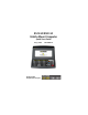
8525 G2/8530 G2 Vehicle-Mount Computer Quick Start Guide May 8, 2006 ISO 9001 Certified Quality Management System PN 8100001.
© Copyright 2006 by Psion Teklogix Inc., Mississauga, Ontario, Canada This document and the information it contains is the property of Psion Teklogix Inc., is issued in strict confidence, and is not to be reproduced or copied, in whole or in part, except for the sole purpose of promoting the sale of Psion Teklogix manufactured goods and services.
Return-To-Factory Warranty Psion Teklogix provides a return to factory warranty on this product for a period of twelve (12) months in accordance with the Statement of Limited Warranty and Limitation of Liability provided at www.psionteklogix.com/ warranty. (If you are not already a member of Teknet and you attempt to view this warranty, you will be asked to register. As a member of Teknet, you’ll have access to helpful information about your Psion Teklogix products at no charge to you.
For a list of international subsidiaries, please go to: www.psionteklogix.com/public.aspx?s=us&p=Contacts. Restriction On Hazardous Substances (RoHS) Directive 2002/95/EC What is RoHS? The European Union has mandated that high environmental standards be met in the design and manufacture of electronic and electrical products sold in Europe, to reduce hazardous substances from entering the environment.
Disclaimer Every effort has been made to make this material complete, accurate, and upto-date. In addition, changes are periodically added to the information herein; these changes will be incorporated into new editions of the publication. Psion Teklogix Inc.
Table Of Contents Approvals And Safety Summary . . . . . . . . . . . . . . . . . . . . . . . 3 Program License Agreements . . . . . . . . . . . . . . . . . . . . . . . . . 9 1. Basic Preparation . . . . . . . . . . . . . . . . . . . . . . . . . . . . . . . . . 15 1.1 Vehicle-Mount Safety Instructions . . . . . . . . . . . . . . . . 15 1.2 8525 G2/30 G2 Freezer & Outdoor Guidelines . . . . . . 16 1.2.1 Important Operating Instructions . . . . . . . . . . . . 16 1.3 Switching The Unit On. . . . . . . . . . .
2.5.3 Onscreen Indicators . . . . . . . . . . . . . . . . . . . . . . 33 2.5.4 Audio Indicators . . . . . . . . . . . . . . . . . . . . . . . . . 37 2.6 Monitoring The Network Connection . . . . . . . . . . . . . 38 2.7 Scanning Techniques . . . . . . . . . . . . . . . . . . . . . . . . . . 38 2.7.1 Scan LED Indicators. . . . . . . . . . . . . . . . . . . . . . 39 3. Navigating In Windows CE. . . . . . . . . . . . . . . . . . . . . . . . . . 39 3.1 Navigating A Touchscreen . . . . . . . . . . . . . . . . .
Approvals And Safety Summary CE Marking When used in a residential, commercial or light industrial environment the product and its approved UK and European peripherals fulfil all requirements for CE marking. R&TTE Directive 1999/5/EC This equipment complies with the essential requirements of EU Directive 1999/5/EC (Declaration available: www.psionteklogix.com). Cet équipement est conforme aux principales caractéristiques définies dans la Directive européenne RTTE 1999/5/CE.
Dette udstyr opfylder de Væsentlige krav i EU's direktiv 1999/5/EC om Radio- og teleterminaludstyr. (Erklæring findes på: www.psionteklogix.com). Dette utstyret er i overensstemmelse med hovedkravene i R&TTEdirektivet (1999/5/EC) fra EU. (Erklæring finnes på: www.psionteklogix.com). Utrustningen uppfyller kraven för EU-direktivet 1999/5/EC om ansluten teleutrustning och ömsesidigt erkännande av utrustningens överensstämmelse (R&TTE). (Förklaringen finns att läsa på: www.psionteklogix.com).
L Use of the 802.11 8525 G2/8530 G2 in France: Owing to French Government restrictions, the 802.11 8525 G2/ 8530 G2 is limited to indoor use. They may be used outdoors, on private property, only with prior authorization from the French Ministry of Defense. FCC Information To Users Federal Communication Commission Interference Statement This equipment has been tested and found to comply with the limits for a Class B digital device, pursuant to Part 15 of the FCC Rules.
FCC Caution: Any changes or modifications not expressly approved by the party responsible for compliance could void the user's authority to operate this equipment. IMPORTANT NOTE: FCC Radiation Exposure Statement: This transmitter must not be co-located or operating in conjunction with any other antenna or transmitter. Some equipment in hospitals and aircraft are not shielded from radio frequency energy. Do not use the 8525 G2/8530 G2 onboard aircraft, or in hospitals, without first obtaining permission.
Cet appareil numérique de la classe B respecte toutes les exigences du Règlement sur le matériel brouilleur du Canada. En cas d’utilisation du module radio 802.11, afin d'éviter toute interférence radio avec le service autorisé, l'appareil doit être utilisé à l'intérieur, tout en tant éloigné de toute fenêtre afin de garantir le maximum de protection. Si cet équipement (ou son antenne émettrice) est installé à l'extérieur, il est alors soumis à licence.
CAUTION Do not operate the vehicle-mount computer with a damaged cord or plug. Replace immediately. CAUTION Make sure the cord is positioned so that it is not stepped on, tripped over or otherwise subjected to damage or stress. CAUTION An extension cord should not be used unless absolutely necessary. Use of an improper extension cord could result in fire or electric shock.
Program License Agreements Microsoft's End User License Agreement You have acquired a device (“DEVICE”) that includes software licensed by Psion Teklogix Inc. from Microsoft Licensing Inc. or its affiliates (“MS”). Those installed software products of MS origin, as well as associated media, printed materials, and “online” or electronic documentation (“SOFTWARE”) are protected by international intellectual property laws and treaties. The SOFTWARE is licensed, not sold. All rights reserved.
• • • • 10 not designed, manufactured, or intended for use or resale as online control equipment in hazardous environments requiring fail-safe performance, such as in the operation of nuclear facilities, aircraft navigation or communication systems, air traffic control, direct life support machines, or weapons systems, in which the failure of Java technology could lead directly to death, personal injury, or severe physical or environmental damage. Sun Microsystems, Inc.
Psion Teklogix Inc. End User License Agreement IMPORTANT - READ CAREFULLY: This License Agreement (“Agreement”) is a legal agreement between you and Psion Teklogix (“we”), the licensor of this software package (“Software”), for your use of the Software only as authorized in this Agreement. By clicking on the “Accept” or other appropriate assent button and/or installing the Software, you agree to be and are hereby bound by the terms and conditions of this Agreement.
the license as described below, the evaluation license shall expire upon the expiration of the evaluation period. c. License Registration. You will be required to provide a license ID, unique to each device, for registering your Software license. As part of your software license registration, we will provide you a corresponding license key for each device. d. No Modifications.
WARE IS PROVIDED “AS-IS” WITHOUT ANY WARRANTY WHATSOEVER AND WITHOUT ANY TECHNICAL SUPPORT OF ANY KIND. WE DISCLAIM ANY AND ALL REPRESENTATIONS, WARRANTIES AND CONDITIONS, WHETHER EXPRESS OR IMPLIED, INCLUDING, BUT NOT LIMITED TO, THE IMPLIED WARRANTIES OR CONDITIONS OF MERCHANTABLE QUALITY OR FITNESS FOR A PARTICULAR PURPOSE.
7. CONFIDENTIALITY You agree not to use or disclose any proprietary information provided by us, except for the purposes of this Agreement. You agree not to reproduce any of the copyrighted materials unless expressly permitted by this Agreement. 8. ENDING THIS AGREEMENT We may terminate this Agreement and your license immediately without notice if (a) you fail to comply with any term of this Agreement, or (b) your rights are assigned by you, by operation of law or otherwise.
1. Basic Preparation Important: All approval and safety information is outlined in the ‘8525 G2/8530 G2 Vehicle-Mount Computer User Manual’ – part number 8000083. It is important that you review all safety guidelines before charging a battery or operating a scanner. This quick start guide provides basic information on the operation and features of the Psion Teklogix 8525 G2/8530 G2 vehicle-mount computers.
• • • • • • • The extension cord is properly wired and in good electrical condition and that the wire size is larger than 16 AWG. When connected to the battery or AC adaptor, the mains power cord shall comply with National safety regulations of the country where the equipment is to be used. Do not operate the battery or AC adaptor with a damaged cord or plug. Replace it immediately.
maintain the temperature, units should be switched on before entry into a freezer environment and should be left connected to vehicle power and running at all times while in a freezer environment. • When moving between freezer and warm, humid environments, window condensation or icing on the outside of the display window is a normal occurrence. Wiping the condensation from the window may help, but the operator may need to wait until the condensation stops forming before use.
will switch back on when external power is restored or the battery temperature is above +10° C. Temperature -30° C (-22° F) Backup Battery Capacity 35% -20° C (-4° F) 45% 0° C (32° F) close to 80% -10° C (14° F) 60% Warning: Do not install the 8525 G2/8530 G2 in such a way that the power cable is bent 90 degrees as this may damage the power cable and power cable strain relief.
To switch off the 8525 G2: • Press the [BLUE] key, and then press the [ENTER/ON] key. Turning off the 8525 G2/8530 G2 does not result in a complete reboot; rather, the unit enters a power-saving, “suspend” state. When the 8525 G2/8530 G2 is turned on from suspend state, operation resumes within a few seconds. Important: If the word ‘BLUE’ is displayed in uppercase in the taskbar at the bottom of the screen, this key is locked ‘on’ – the 8525 G2/8530 G2 will not switch off.
1.5 Connecting To An 802.11 Network In most cases, the 8525 G2/8530 G2 must be configured before it can connect to an 802.11 wireless network. The 8525 G2/8530 G2 Vehicle-Mount Computer User Manual (PN 8000083) describes this configuration process. Refer to “Configuring An IEEE 802.11 Radio” in Chapter 2: Basic Checkout for details. Once the 8525 G2/ 8530 G2 is properly configured, it automatically connects to your wireless network within a few moments of switching on.
2. Getting To Know Your 8525 G2/8530 G2 2.1 8525 G2/8530 G2 Features Inside The Radio Dome - SDIO/MMC Slot – for additional storage memory - PCMCIA slot - supports 2-Type II PCMCIA or 1-Type III PCMCIA card - Compact Flash slot - for 802.
2.1.1 8525 G2 Ports Tether Port RS232 Serial Port Auxiliary Port 2.1.
Keyboard Port 2.2 The Internal Backup Battery The 8525 G2/8530 G2 vehicle-mount is equipped with an internal battery that will provide backup power to the unit for up to fifteen minutes of normal operation. After 15 minutes, the unit will shut off to preserve the contents of RAM. The backup battery is not user accessible. It must be replaced by authorized Psion Teklogix personnel. 2.3 The Keyboard The 8525 G2/8530 G2 offers three keyboard layouts – QWERTY, ABC and AZERTY.
2.3.1 Modifier Keys The [SHIFT], [CTRL], [ALT], [BLUE] ad [ORANGE] keys are modifier keys. Pressing a modifier key changes the function of the next key pressed. For example, on a QWERTY keyboard, a square bracket is printed in orange print above the [4] key. Pressing the [ORANGE] key followed by the [4] key displays a square bracket rather than the number 4. The [SHIFT], [CTRL] and [ALT] keys operate much like a desktop keyboard except that they are not chorded (two keys held down simultaneously).
2.3.2 The Keys The [BLUE] And [ORANGE] Keys The [BLUE] and [ORANGE] modifier keys provide access to additional symbols and keys. These additional symbols and keys are colour coded in blue and orange print above the keyboard keys. • Press the [BLUE] key to access functions or characters displayed in blue print on the keyboard. Press the [ORANGE] key to access functions or characters displayed in orange print on the keyboard.
The [CTRL] And [ALT] Key The [CTRL] and [ALT] keys modify the function of the next key pressed and are application dependent. The [TAB] Key Typically, the [TAB] key moves the cursor to the next field to the right or downward. The [ESC] Key Generally, this key is used as a keyboard shortcut to close the current menu, dialog box or activity and return to the previous one. The [SPACE] Key Pressing this key inserts a blank space between characters.
application. Refer to the manual provided with your application for details. 2.3.3 Adjusting The Keypad Backlight Note: If you’re uncertain how to access the Control Panel, refer to “The Start Menu” on page 43. To adjust the intensity of the keypad backlight and the conditions under which this backlight is activated. • In the Control Panel, choose the Keyboard icon. • In the Keyboard Properties dialog box, open the Backlight tab.
ON For The value chosen from this dropdown menu determines the duration of time that the keyboard backlight stays on when a unit is not in use. Note:Tapping in the checkbox next to ‘When using external power, keep the backlight always ON’ forces the keypad backlight to remain on when the unit is operating with external power such as a vehicle battery or A/C adaptor. 2.4 The Display 8525 G2/8530 G2s are equipped with display backlighting to improve character visibility in low light conditions.
Intensity This parameter is used to adjust the light intensity of the backlight. Sliding the bar to the left lowers the light intensity, and sliding it to the right raises the intensity. Bright For The value chosen from this dropdown menu determines the duration of time that the backlight stays on at the configured intensity when a unit is not in use.
• Choose the Calibration tab, and then tap on the Recalibrate button. • Follow the directions on the calibration screen to calibrate the screen. 2.5 8525 G2/8530 G2 Indicators 8525 G2/8530 G2s use LEDs (Light Emitting Diodes), onscreen messages and audio tones as indicators. The vehicle-mount is also equipped with a power indicator LED. 2.5.1 Power Indicator LED A power indicator LED is located in the radio dome at the top of the unit.
2.5.2 LEDs The 8525 G2/8530 G2 is equipped with four tri-coloured LEDs located in the upper-right corner of the keyboard. If you have an 8530 G2 and are using the onscreen, soft keyboard, only the API and Rx/Tx LEDs are available in the taskbar. Important: You should proceed cautiously if a LED is illuminated in red; this generally indicates an abnormal operating condition or an active laser emission.
PWR/CHG – Charge LED The lower-right LED is reserved for internal charger/power status. This LED operates as follows: LED Behaviour Description Solid green Slow flashing green External power in use. Backup battery is present. External power in use. Backup battery not present. External power not in use. Unit drawing power from backup battery.
API – User Application LED This indicator is available for user-loaded custom Windows CE applications. Refer to the 8525/8530 SDK Manual for details about this LED. Neither Windows CE nor Tekterm use this LED. 2.5.3 Onscreen Indicators The taskbar at the bottom of the screen displays a variety of system status indicators. The taskbar changes dynamically, and only those icons that are applicable are displayed.
[SHIFT], [CTRL], [ALT], [BLUE] and [ORANGE] are modifier keys that have onscreen indicators to show when a key is active or locked. If when you press a modifier key, it is displayed in the taskbar in lowercase characters, this indicates that the key will remain active only until the next key is pressed.
External DC Power This external DC power icon is displayed in the taskbar when the unit is using external DC power and the backup battery is not present. Onscreen LEDs (8530 G2 Only) When the 8530 G2 keyboard is removed, two onscreen-LEDs are displayed in the taskbar. The left LED acts as the API indicator, and the right LED acts as the TX/RX (transmit and receive) indicator. These onscreen LEDs behave in the same way as those on the keyboard, changing colour to indicate different operations.
Narrow Band Radio Signal Quality Increasing radio signal quality is represented by longer, filled bars within this icon. Good Reception Weak Reception No Radio Link The radio signal is determined when the 8525 G2/8530 G2 receives a message. If the unit receives no messages within a second, the “no signal” icon is displayed. The signal strength icon shows the following cases: No signal, 1% to 25% bar, 26% to 50% bar, 51% to 75% bar and 75% to 100% bar.
Bluetooth Radio This icon indicates that a Bluetooth radio is installed in your unit. Input Panel Button (8530 G2 Only) Tapping on the Input Panel Button in the taskbar displays a soft keyboard on the 8530 G2 screen. Use the stylus to tap on the keys. Keep in mind that the soft keyboard is not displayed when a physical keyboard is attached to the vehicle-mount. 2.5.
To adjust the beeper volume: • Lock the [BLUE] key ‘on’. • Press the increase volume key or the decrease volume key until the volume meets your needs. • Press the [BLUE] key again to ‘unlock’ it. 2.6 Monitoring The Network Connection If your vehicle-mount is equipped with a wireless-LAN radio, it will typically associate with the nearest access point. The radio signal quality meter in the taskbar indicates the relative strength of the communication link.
• If you are using a 2D imaging scanner, make certain the red, oval-shaped framing mark is centered within the bar code you want to scan. • Hold the scanner farther away for larger bar codes. • Hold the scanner closer for bar codes with bars that are close together. 2.7.1 Scan LED Indicators The 8525 G2/8530 G2 scanner LED (the upper-right LED) indicates whether or not your scan is successful.
than a mouse. Actions can be performed using any combination of keyboard shortcuts or touchscreen tapping. 3.1 Navigating A Touchscreen Note: If the touchscreen is not registering your screen taps accurately, it may need recalibration. Refer to “Calibrating The Touchscreen” on page 29. Units are equipped with a stylus—a pointing tool that looks like a pen. It is used to select objects on the touchscreen. Note: To prevent damage to the touchscreen, use only the stylus (pen) supplied with your unit.
Open file, folder or icon [ENTER] Exit & Save [ENTER] Close/Exit & Do Not Save [ESC] Navigate Dialog Boxes [TAB] To move cursor up: [SHIFT][TAB] To display the next ‘tab’ in a dialog box: [CTRL][TAB] Select Radio Button/ Press Button [SPACE] Go to Start Menu [BLUE][0] 3.3 The Startup Desktop When the 8525 G2/8530 G2 boots up, the startup desktop is displayed. Any applications stored in the Startup folder will start up immediately. 3.3.
Start Menu, and choose Desktop. Now the desktop will be “in focus” and the arrow keys will highlight the icons. If you’re using a touchscreen: • Tap an icon to select it, double-tap on it to open a dialog box or, in the case of an application icon, launch an application. 3.3.2 The Taskbar The 8525 G2/8530 G2 has a taskbar at the bottom of the screen. It displays icons through which you can view the internal battery capacity, the radio signal quality of your unit, and so on.
• Press the [LEFT] and [RIGHT] arrow keys to highlight the icon in the taskbar about which you’d like more information. A tooltip is displayed as each taskbar icon is highlighted. The tooltip provides the status of each icon. • Press [ENTER] to display the associated dialog box. If you’re using touchscreen: • Tap and hold the stylus on an icon to display the icon's tooltip. Double-tap the icon to open the Control Panel dialog box associated with the icon. 3.
If you’re using a touchscreen: • Tap on the Start button in the taskbar. Tap on the item in the menu with which you want to work. The Desktop Choosing Desktop from the Start Menu displays the 8525 G2/ 8530 G2 desktop. Security Settings To assign a security level: • Choose Security from the Start Menu. • Choose a security level from the dialog box. To allow access to all the Start Menu and taskbar options, choose the Supervisor security level.
Programs The Programs menu contains a sub-menu of programs available on your vehicle-mount. Shortcuts The System Tray If the touchscreen has been disabled, the System Tray option in the Shortcuts sub-menu allows access to the icons in the taskbar at the bottom of the screen. The taskbar displays indicators such as a battery capacity gauge and the security level. These indicators are attached to dialog boxes that provide additional information. • Choose System Tray from the Start Menu.
When System Tray is chosen, the taskbar icons become accessible. To display the dialog box attached to an icon: • Use the [LEFT] and [RIGHT] arrow keys to highlight an icon—for example, the security icon. • Press [ENTER] to display the security level dialog box. If you’re using a touchscreen, you don’t need to use System Tray option. You have direct access to the icons in the taskbar. • Tap and hold the stylus on a taskbar icon to display a tooltip – a brief description of the status of the icon.
Press [ALT][ESC]. Settings The Settings menu provides access to the Control Panel applets, lets you configure your radio (Network and Dial-up Connections) and customize the Taskbar and Start Menu.
Run Choosing the Run option displays a dialog box in which you can enter the name of the program, folder or document you want to open. Shutdown Suspends the 8525/30 G2 immediately – equivalent to turning the unit off. Resets the 8525/30 G2, leaving all saved files and (registry) settings intact. Unsaved data is lost. Resets the 8525/30 G2. Files stored outside of permanent memory are lost. Note: The Shutdown menu varies depending on the security level chosen.
3.5 Using A Dialog Box A dialog box appears when you need to make selections and enter further information. Checkbox Dropdown Menu Button Tabs Radio Button Textbox Important: If you’re using a touchscreen, use the stylus to tap on an element in a dialog box to select or deselect it, display dropdown menus, save your selections, and so on. If you’re using a keyboard, follow the directions in this section.
Dialog boxes contain one or more of the following elements: Tab: A tab separates different elements of a dialog box. Press the [TAB] key until a tab in the dialog box is highlighted. To display adjoining tabs, press the [RIGHT] or [LEFT] arrow key. To display the information in the next tab from anywhere in the window, press [CTRL] [TAB]. Textbox: A textbox requires that you type information. Press the [TAB] key to highlight the textbox and then type the appropriate information.
4. General Maintenance 4.1 Caring For The Touchscreen The top of the touchscreen is a thin, flexible polyester plastic sheet with a conductive coating on the inside. The polyester can be permanently damaged by harsh chemicals and is susceptible to abrasions and scratches. Using sharp objects on the touchscreen can scratch or cut the plastic, or crack the internal conductive coating. If the touchscreen is used in harsh environments, consider applying a disposable screen protector (PN 1008009).
5. Support Services & Worldwide Offices Psion Teklogix provides a complete range of product support services to its customers worldwide. These services include technical support and product repairs. 5.1 Technical Support Technical Support for Mobile Computing Products is provided via e-mail through the Psion Teklogix customer and partner extranets. To reach the website, go to www.psionteklogix.com and click on the appropriate Teknet link on the home page.
5.3 Worldwide Offices COMPANY HEADQUARTERS AND CANADIAN SERVICE CENTRE Psion Teklogix Inc. 2100 Meadowvale Blvd. Mississauga, Ontario Canada L5N 7J9 Tel: +1 905 813 9900 Fax: +1 905 812 6300 E-mail: salescdn@psion.com NORTH AMERICAN HEADQUARTERS AND U.S. SERVICE CENTRE Psion Teklogix Corp. 1810 Airport Exchange Boulevard Suite 500 Erlanger, Kentucky USA 41018 Tel: +1 859 371 6006 Fax: +1 859 371 6422 E-mail: salesusa@psion.com INTERNATIONAL SUBSIDIARIES (SEE ALSO WWW.PSIONTEKLOGIX.COM) Psion Teklogix S.A.