WORKABOUT PRO Hand-Held (Model Numbers 7527C-G2 & 7527S-G2) Computer With Windows Mobile 6 Classic & Professional User Manual August 9, 2007 ISO 9001 Certified Quality Management System Part No. 8100144.
© Copyright 2007 by Psion Teklogix Inc., Mississauga, Ontario This document and the information it contains is the property of Psion Teklogix Inc., is issued in strict confidence, and is not to be reproduced or copied, in whole or in part, except for the sole purpose of promoting the sale of Teklogix manufactured goods and services. Furthermore, this document is not to be used as a basis for design, manufacture, or sub-contract, or in any manner detrimental to the interests of Psion Teklogix Inc.
Disclaimer Every effort has been made to make this material complete, accurate, and up-to-date. In addition, changes are periodically added to the information herein; these changes will be incorporated into new editions of the publication. Psion Teklogix Inc.
TABLE OF CONTENTS Chapter 1: Introduction 1.1 1.2 1.3 About This Manual . . . . . . . . . . . . . . . Text Conventions . . . . . . . . . . . . . . . . WORKABOUT PRO Features . . . . . . . . . 1.3.1 The WORKABOUT PRO C Hand-Held 1.3.2 The WORKABOUT PRO S Hand-Held . . . . . . . . . . . . . . . . . . . . . . . . . . . . . . . . . . . . . . . . . . . . . . . . . . . . . . . . . . . . . . . . . 3 4 4 6 7 Chapter 2: Basic Checkout 2.1 2.2 2.3 2.4 2.5 2.6 2.7 2.
Contents 2.9 2.8.1.3 Receive An Incoming Call . . . . . . . . . . . . . . 2.8.1.4 Program Speed Dial . . . . . . . . . . . . . . . . . . 2.8.2 Send & End Calls Using The WORKABOUT PRO Keyboard . 2.8.3 Managing Phone Settings . . . . . . . . . . . . . . . . . . . . 2.8.3.1 Phone Tab . . . . . . . . . . . . . . . . . . . . . . . 2.8.3.2 Services Tab . . . . . . . . . . . . . . . . . . . . . . 2.8.3.3 Network Tab . . . . . . . . . . . . . . . . . . . . . . Resetting The WORKABOUT PRO Hand-Held . . . . . . .
Contents 3.6.1 The LED . . . . . . . . . . . . . . . . . . . . . . . . . . 3.6.2 Audio Indicators . . . . . . . . . . . . . . . . . . . . . . 3.6.2.1 Adjusting Speaker Volume . . . . . . . . . . . 3.7 Monitoring The Battery And Maximizing Run Time. . . . . . . 3.7.1 Storing Batteries . . . . . . . . . . . . . . . . . . . . . . 3.8 Uploading Data In A Docking Station . . . . . . . . . . . . . . 3.9 Bluetooth Radio . . . . . . . . . . . . . . . . . . . . . . . . . . 3.9.
Contents 4.6 4.7 4.8 4.9 4.10 4.5.1 Pop-Up Menus . . . . . . . . . . . . . . . The Softkey Bar . . . . . . . . . . . . . . . . . . Programs–Using Applications . . . . . . . . . . . Settings. . . . . . . . . . . . . . . . . . . . . . . Help . . . . . . . . . . . . . . . . . . . . . . . . Entering Text. . . . . . . . . . . . . . . . . . . . 4.10.1 Soft Keyboard . . . . . . . . . . . . . . . 4.10.2 The Transcriber. . . . . . . . . . . . . . . 4.10.3 Block Recognizer And Letter Recognizer . . . . . . . . . .
Contents 5.12 5.13 5.14 5.15 5.16 5.17 5.18 5.19 5.20 5.21 5.22 5.23 5.24 5.25 5.26 5.27 System Tab Settings . . . . . . . . . . . . . . . . . . . . . . . . . . About . . . . . . . . . . . . . . . . . . . . . . . . . . . . . . . . . About Device . . . . . . . . . . . . . . . . . . . . . . . . . . . . . Backlight . . . . . . . . . . . . . . . . . . . . . . . . . . . . . . . 5.15.1 Battery Power . . . . . . . . . . . . . . . . . . . . . . . . . 5.15.2 External Power. . . . . . . . . . . . . . . . . . . .
Contents 5.27.1.4 Data Options–Decoded (Internal) Scanner 5.27.1.5 Code 39 . . . . . . . . . . . . . . . . . . 5.27.1.6 Code 128. . . . . . . . . . . . . . . . . . 5.27.1.7 EAN 13 . . . . . . . . . . . . . . . . . . 5.27.1.8 EAN 8 . . . . . . . . . . . . . . . . . . . 5.27.1.9 UPC A . . . . . . . . . . . . . . . . . . . 5.27.1.10 UPC E . . . . . . . . . . . . . . . . . . . 5.27.1.11 UPC/EAN Shared Settings . . . . . . . . 5.27.1.12 Code 93 . . . . . . . . . . . . . . . . . . 5.27.1.13 Codabar . . . . . . .
Contents 5.27.2.24 5.27.2.25 5.27.2.26 5.27.2.27 5.27.2.28 5.27.2.29 5.27.2.30 5.27.2.31 5.27.2.32 5.27.2.33 5.27.2.34 5.27.2.35 5.27.2.36 5.27.2.37 5.27.2.38 5.27.2.39 5.27.2.40 5.27.2.41 5.27.3 Decoded 5.27.3.1 5.27.3.2 5.27.3.3 5.27.3.4 5.27.3.5 5.27.3.6 5.27.3.7 5.27.3.8 5.27.3.9 5.27.3.10 5.27.3.11 5.27.3.12 5.27.3.13 5.27.3.14 5.27.3.15 5.27.3.16 5.27.3.17 5.27.3.18 5.27.3.19 5.27.3.20 5.27.3.21 5.27.4 Imager . PDF-417 . . . . . . . . . . . . . . . . . Micro PDF-417 . . . . . . . . . . . . . .
Contents 5.28 5.29 5.30 5.31 viii 5.27.4.1 Options–Imager . . . . . . . . . . . . . 5.27.4.2 Advanced Options – Imager. . . . . . . 5.27.4.3 Code 39 Settings. . . . . . . . . . . . . 5.27.4.4 Code 128 Settings . . . . . . . . . . . . 5.27.4.5 EAN 13 . . . . . . . . . . . . . . . . . 5.27.4.6 EAN 8 . . . . . . . . . . . . . . . . . . 5.27.4.7 UPC A . . . . . . . . . . . . . . . . . . 5.27.4.8 UPC E . . . . . . . . . . . . . . . . . . 5.27.4.9 Code 93 . . . . . . . . . . . . . . . . . 5.27.4.10 Codabar .
Contents 5.32 5.33 5.34 5.35 5.31.4 Outgoing Port . . . . . . . . . . . . . . . . . . . . . . . . . 5.31.5 Active Connections List . . . . . . . . . . . . . . . . . . . . 5.31.6 About Tab . . . . . . . . . . . . . . . . . . . . . . . . . . . 5.31.7 The Bluetooth GPRS Phone . . . . . . . . . . . . . . . . . . Connections – Connecting To The Internet . . . . . . . . . . . . . . 5.32.1 Modem Connection Setup . . . . . . . . . . . . . . . . . . . 5.32.1.1 Advanced Modem Settings . . . . . . . . . . . . .
Contents 5.35.6.4 SMS Configuration . . . . . . . . . . . . . . . . . . 241 Chapter 6: Programs 6.1 6.2 6.3 Programs . . . . . . . . . . . . . . . . . . . . . . . Games . . . . . . . . . . . . . . . . . . . . . . . . ActiveSync®. . . . . . . . . . . . . . . . . . . . . 6.3.1 Synchronization . . . . . . . . . . . . . . . 6.4 Calculator . . . . . . . . . . . . . . . . . . . . . . 6.5 Demo Scanner . . . . . . . . . . . . . . . . . . . . 6.6 Office Mobile . . . . . . . . . . . . . . . . . . . . 6.6.
Contents 6.13 Messaging . . . . . . . . . . . . . . . . . . . . . 6.13.1 Folders . . . . . . . . . . . . . . . . . . . 6.13.2 Synchronizing E-mail With Outlook . . . 6.13.3 Changing Synchronization Settings . . . . 6.14 Tasks. . . . . . . . . . . . . . . . . . . . . . . . 6.15 Remote Desktop Mobile . . . . . . . . . . . . . 6.15.1 Connecting To A Terminal Server . . . . 6.15.2 Disconnecting Without Ending A Session 6.15.3 Ending A Session . . . . . . . . . . . . . 6.16 Windows Media . . . . . . . . . . . .
Contents 7.7 7.8 7.9 7.10 7.11 7.12 7.13 xii Cigarette Lighter Adaptor–Model #WA3113-G2 . . . . . . . . . . Single Battery Charger–Model #WA3001-G1. . . . . . . . . . . . 7.8.1 Inserting A Battery In The Single Battery Charger . . . . . 7.8.2 Battery Charge Duration . . . . . . . . . . . . . . . . . . . 7.8.3 Charge Indicators–The LED . . . . . . . . . . . . . . . . . Quad Battery Charger–Model #WA3004-G1 . . . . . . . . . . . . 7.9.1 Charging Batteries . . . . . . . . . . . . . . . . . . . . . . 7.9.
Contents 7.13.3 Operating One Dimensional (1D) Laser Scanners . . . . . . . 292 7.13.4 Operating Two Dimensional (2D) Imagers . . . . . . . . . . . 292 7.14 Bluetooth Peripherals . . . . . . . . . . . . . . . . . . . . . . . . . . 293 Chapter 8: Specifications 8.1 8.2 8.3 8.4 8.5 Hand-Held Computer Specifications . . . . . . . . . . . . . Radio Specifications. . . . . . . . . . . . . . . . . . . . . . Battery Specifications . . . . . . . . . . . . . . . . . . . . . 8.3.1 High-Capacity (Model WA3006) . .
Contents A.3.3 ThirdPartyConfig A.4 Global Settings Tab . . . A.5 Status Tab . . . . . . . . A.6 Diags Tab . . . . . . . . . . . . . . . . . . . . . . . . . . . . . . . . . . . . . . . . . . . . . . . . . . . . . . . . . . . . . . . . . . . . . . . . . . . . . . . . . . . . . . . . . . . . . . . . . . . . .A-6 .A-7 .A-9 A-10 B.1 LIF (Low Insertion Force) Port Pinout . . . . B.2 Tether Port Pinout . . . . . . . . . . . . . . . B.3 Battery Contact Pinout–WA3006 & WA3010 . B.3.
1 INTRODUCTION 1.1 About This Manual . . . . . . . . . . . . . . . 1.2 Text Conventions . . . . . . . . . . . . . . . . 1.3 WORKABOUT PRO Features . . . . . . . . . 1.3.1 The WORKABOUT PRO C Hand-Held . 1.3.2 The WORKABOUT PRO S Hand-Held . . . . . . . . . . . . . . . . . . . . . . . . . . . . . . . . . . . . . . . . . . . . . . . . . . . . . . . . . . . . . . . . . . . . . . . .3 .4 .4 .6 .
Chapter 1: Introduction About This Manual 1.1 About This Manual This manual describes how to configure, operate and maintain the WORKABOUT PRO (Model Numbers 7527C-G2 and 7527S-G2) hand-held computer. Chapter 1: Introduction provides a basic overview of the WORKABOUT PRO hand-held. Chapter 2: Basic Checkout describes the steps required to get the unit ready for operation. Chapter 3: Getting To Know The WORKABOUT PRO describes the features and outlines how to charge and maintain the battery.
Chapter 1: Introduction Text Conventions 1.2 Text Conventions Note: Notes highlight additional helpful information. Important: These statements provide particularly important instructions or additional information that is critical to the operation of the equipment. Warning: These statements provide critical information that may prevent physical injury, equipment damage or data loss. 1.
Chapter 1: Introduction WORKABOUT PRO Features Operating System • • Microsoft Windows Mobile 6 Professional Microsoft Windows Mobile 6 Classic Multi-Media Chipset • NVIDIAGoForce 4000 Multi-Media Processor Real-Time Clock • CPU independent RTC capable of maintaining the system date and time for at least 3 months with a fully charged backup battery User Interface • • • Color Touchscreen Display 3.6 in.(9.
Chapter 1: Introduction The WORKABOUT PRO C Hand-Held • Note: • Voice and Data • GPRS Class B, Multi-Slot Class 12 • EGPRS Class B,Multi-Slot Class 12 Integrated Bluetooth class II, ver 1.2 • Working Range: 16.4 ft.to 32.81 ft. (5m to 10m) 802.11b/g, GSM, and Bluetooth are available simultaneously. 1.3.1 The WORKABOUT PRO C Hand-Held Figure 1.
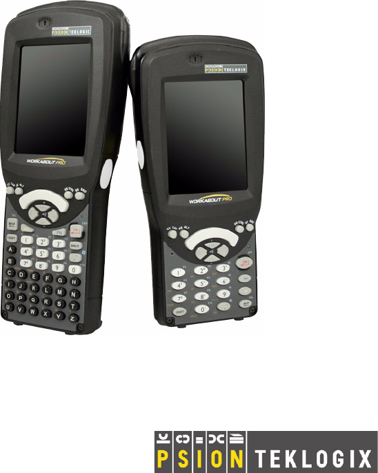
Chapter 1: Introduction The WORKABOUT PRO S Hand-Held 1.3.2 The WORKABOUT PRO S Hand-Held Figure 1.2 WORKABOUT PRO S With 25-Key Keyboard End Talk Figure 1.3 Phone Labels Note: The [Talk] and [End] phone keys printed on the hand-held shown in the drawing above are useful for units equipped with Windows Mobile 6 Professional that support the phone feature. Refer to “Send & End Calls Using The WORKABOUT PRO Keyboard” on page 25 for details.
2 BASIC CHECKOUT 2.1 Preparing The WORKABOUT PRO For Operation . . . . . . . . . 2.1.1 The Main Battery . . . . . . . . . . . . . . . . . . . . . . . . 2.1.1.1 Charging The Main Battery . . . . . . . . . . . . . . 2.1.2 The Backup Battery. . . . . . . . . . . . . . . . . . . . . . . 2.1.2.1 Backup Battery Gas Gauge . . . . . . . . . . . . . . 2.2 Turning The WORKABOUT PRO On and Off. . . . . . . . . . . . 2.2.1 Installing The Battery And Switching The Unit On . . . . . . 2.2.
Chapter 2: Basic Checkout Preparing The WORKABOUT PRO For Operation 2.1 Preparing The WORKABOUT PRO For Operation 2.1.1 The Main Battery Warning: Before charging the battery, it is critical that you review the battery safety guidelines in the “WORKABOUT PRO Hand-Held Computer Warranty & Regulatory Guide”, PN 8000126. The WORKABOUT PRO C and WORKABOUT PRO S can be powered with one of the following lithium-ion battery packs: • High-Capacity – Model No. WA3006, and • Super High-Capacity – Model No.
Chapter 2: Basic Checkout The Backup Battery 2.1.2 The Backup Battery To preserve data stored in your WORKABOUT PRO while you swap the main battery, the unit is equipped with an internal backup battery–a replaceable, rechargeable Lithium-Ion backup battery that can be ordered through Psion Teklogix. The backup battery will supply 5 minutes of continuous power while you install a charged, main battery. The backup battery is trickle charged from the main battery.
Chapter 2: Basic Checkout Turning The WORKABOUT PRO On and Off 2.2 Turning The WORKABOUT PRO On and Off 2.2.1 Installing The Battery And Switching The Unit On Important: • • • • Note: If the unit is currently on, press [FN/BLUE] [ENTER] to turn off the hand-held before opening the battery cover on your WORKABOUT PRO.
Chapter 2: Basic Checkout The Getting Started CD 2.3 The Getting Started CD The Getting Started CD shipped with your unit runs automatically when inserted, Displaying a start-up screen.
Chapter 2: Basic Checkout The Getting Started CD Tapping on Next in the start-up screen displays a screen listing your setup and installation options. Tapping on one of the following options provides the following options: Setup and Installation–allows you to install the Windows Mobile® Device Handbook and ActiveSync. When you tap on this option, only items that are not already present on your PC are installed.
Chapter 2: Basic Checkout Connecting The WORKABOUT PRO To A PC 2.4 Connecting The WORKABOUT PRO To A PC Note: Refer to “Linking A WORKABOUT PRO To A PC” on page 277 for more details about the desktop docking station and how to link to a PC. The WORKABOUT PRO can be connected to a PC using the desktop docking station. • Insert the unit in the desktop docking station. • Use a Client USB connector to complete the communication link between the hand-held and the PC. 2.
Chapter 2: Basic Checkout Aligning (Calibrating) The Touchscreen 2.6 Aligning (Calibrating) The Touchscreen Refer to “Aligning (Calibrating) The Touchscreen” on page 44 for details. 2.7 Setting Up A RA2041 Radio–Summit Client Utility This section describes the steps required to set up the RA2041 Summit Radio using the Summit Client Utility (SCU). To review details about the option within the SCU tabs – Main, Config, Status, Diags and Global Settings – review Appendix A: Summit Client Utility (SCU). 2.7.
Chapter 2: Basic Checkout Using The SCU To Connect To The WLAN • Tap on Start>Programs, and then tap on the SCU icon. • Tap on the Config tab. • • Tap on New to define a new config. Type a name for your configuration using any alpha-numeric combination to uniquely identify this config. Tap on OK to return to the Config tab. Tap on Commit to save the config name. When a pop-up message indicates that your configuration will be saved, tap on OK.
Chapter 2: Basic Checkout Using The SCU To Connect To The WLAN • • Type an SSID in the text box to the right of SSID. This field is limited to 32 characters. Tap on Commit and then, in the pop-up message, tap on OK to save your SSID setting. Important: To learn more about the other options available in the radio attributes list, refer to “Config Tab” in Appendix A: Summit Client Utility (SCU).
Chapter 2: Basic Checkout The Phone (Windows Mobile 6 Professional Only) - Authenticate to the network. - If EAP authentication is being used, derive dynamic encryption keys. - If DHCP is being used by the network, obtain an IP address. If the RA2041 is not connecting properly: • Tap on the Status tab. The Status dialog box lists the IP and MAC address, and indicates the current state of the radio, the signal strength, channel and so on.
Chapter 2: Basic Checkout Make A Conference Call phone number; it is labelled with a green telephone receiver icon.Refer to “Send & End Calls Using The WORKABOUT PRO Keyboard” on page 25 for details. Phone settings Network emergency number Directory Assistance To send a number: • Use the phone keypad to enter the phone number, and tap on Talk to dial the phone number. To end a phone call: • Tap on End button on the phone keypad. Note: 2.8.1.
Chapter 2: Basic Checkout Receive An Incoming Call 2.8.1.3 Receive An Incoming Call To answer an incoming call: • Tap on the [Talk] button located on the [TAB] key on the WORKABOUT PRO keyboard. It’s labelled with a green phone receiver. 2.8.1.4 Program Speed Dial The phone keypad provides a Speed Dial button for quick access to often used numbers. • In the phone keypad, tap on the Speed Dial button to display the speed dial Phone dialog box.
Chapter 2: Basic Checkout Program Speed Dial • In the list, choose a contact for a speed dial. • Tap on Enter a name, and type a contact name, or tap on a name in the list. A sequential speed dial key is automatically assigned in the Location field. You can tap on the Location dropdown menu and change the auto assignment.
Chapter 2: Basic Checkout Program Speed Dial Using The Contact List To Program A Speed Dial 24 • Tap Contact in the softkey bar at the bottom of the Today screen. • Tap on the Contact to which you want to assign a speed dial number. • In the Summary screen, tap on Menu>Add to Speed Dial.
Chapter 2: Basic Checkout Send & End Calls Using The WORKABOUT PRO Keyboard 2.8.2 Send & End Calls Using The WORKABOUT PRO Keyboard WORKABOUT PROs that support the phone feature are equipped with a [Talk] and an [End] phone key; these keys have been mapped to the [TAB] and [ESC] keys, respectively, on the hand-held keyboard. Talk End Using these phone keys, you can display the phone keypad and answer, send and terminate phone calls.
Chapter 2: Basic Checkout Managing Phone Settings 2.8.3 Managing Phone Settings You can adjust phone settings such as the ring type and tone, choose phone services such as barring calls, and you can also determine network selections. There are a number of ways you can access phone settings. • In the Navigation Bar, tap on the Phone Settings hotkey. In the pop-up Phone bubble, tap on Settings, or • Tap on Start>Settings>Phone icon.
Chapter 2: Basic Checkout Services Tab Security This option allows you to assign a PIN so that your hand-held is protected from unauthorized use. Your SIM card manufacturer provides the default PIN which you can change in this field. Change Pin Tapping on this button allows you to change your PIN (Personal Identification Number). Your SIM manufacturer provides a default PIN that you can enter here, and then change.
Chapter 2: Basic Checkout Network Tab • • From a land line, dial your wireless phone number. Allow the hand-held to ring until it is automatically picked up by the voice mail service. At the greeting, type #. You will be prompted to enter your temporary passcode. A tutorial will lead you through the voice mail setup. When you’ve assigned your personalized passcode, keep it in a secure place. 2.8.3.
Chapter 2: Basic Checkout Cold Resetting To The BooSt Menu 2.9.2 Cold Resetting To The BooSt Menu To execute a reset and access the BooSt menu: • Press and hold down the centre [SCAN] bar and then press the [FN/BLUE] and [ENTER] keys simultaneously for a minimum of two seconds. After a reset, the BooSt menu appears, listing possible BooSt commands. • To load the Windows Mobile 6 operating system, type 1. 2.9.
3 GETTING TO KNOW THE WORKABOUT PRO 3.1 Features Of The WORKABOUT PRO . . . . . . . . . . . . . . . . 3.2 The Batteries . . . . . . . . . . . . . . . . . . . . . . . . . . . . . 3.2.1 Battery Safety . . . . . . . . . . . . . . . . . . . . . . . . . . 3.2.2 Removing The Battery Pack . . . . . . . . . . . . . . . . . . 3.2.3 Battery Swap Time . . . . . . . . . . . . . . . . . . . . . . . 3.2.3.1 Safely Swapping The Main Battery . . . . . . . . . . 3.2.4 Charging The Battery . . . . . . . . . . . . . . . . .
Chapter 3: Getting To Know The WORKABOUT PRO 3.10.1 Inserting The Card . . . . . . . . . . 3.11 General Maintenance . . . . . . . . . . . . 3.11.1 Caring For The Touchscreen . . . . . 3.11.2 Cleaning The WORKABOUT PRO . 32 . . . . . . . . . . . . . . . . . . . . . . . . . . . . . . . . . . . . . . . . . . . . . . . . . . . . . . . . . . . . . . . .
Chapter 3: Getting To Know The WORKABOUT PRO Features Of The WORKABOUT PRO 3.1 Features Of The WORKABOUT PRO Speaker LED (Light Emitting Diode) Microphone Microphone Port LED (Light Emitting Diode) Figure 3.
Chapter 3: Getting To Know The WORKABOUT PRO Features Of The WORKABOUT PRO Battery Cover Back Cover Stylus (pointing tool) End Cap Figure 3.2 Back Of WORKABOUT PRO DC IN Socket Low Insertion Force Port (LIF) Tether Port Beeper Port Figure 3.
Chapter 3: Getting To Know The WORKABOUT PRO The Batteries 3.2 The Batteries The hand-held operates with a Lithium-Ion battery pack. Preparing the unit for operation requires that a battery pack be charged and installed in the WORKABOUT PRO. Three levels of battery packs are available for the WORKABOUT PRO: • High-Capacity – Model No. WA3006, and • Super High-Capacity – Model No. WA3010 3.2.
Chapter 3: Getting To Know The WORKABOUT PRO Safely Swapping The Main Battery The Suspend Threshold feature allows you to determine the battery capacity at which the hand-held will be shut down. If left at the default value, Maximum Operating Time, the unit will run until the battery is completely empty; the RAM is only backed up for a short period of time. If you choose Maximum Backup Time, the hand-held shuts off with more energy left in the battery so RAM can be backed up for a longer period of time.
Chapter 3: Getting To Know The WORKABOUT PRO Chargers And Docking Stations IF YOU ARE POWERING UP A NEW UNIT, a warning message may appear on the screen indicating that the backup battery capacity is low. To recharge the backup battery, you must fully charge the WORKABOUT PRO with the main battery installed in the unit. 3.2.4.1 Chargers And Docking Stations Important: FOR DETAILED INFORMATION about chargers and docking stations, refer to Chapter 7: Peripheral Devices & Accessories beginning on page 265.
Chapter 3: Getting To Know The WORKABOUT PRO Switching The Hand-Held On And Off 3.3 Switching The Hand-Held On And Off Switching On The WORKABOUT PRO • Press and hold down the [ENTER] key for at least two seconds. • When the LED flashes green, release the [ENTER] button. The startup Today screen is displayed. Note: If the WORKABOUT PRO is in suspend state, pressing [ENTER] ‘wakes’ the unit from this state. The screen in which you were working before the computer entered suspend state is displayed.
Chapter 3: Getting To Know The WORKABOUT PRO Modifier Keys Note: Almost all keys can be reprogrammed to suit your requirements. 3.4.2 Modifier Keys The [SHIFT], [CTRL], [ALT], [FN/BLUE] and [FN/ORANGE] keys are modifier keys. Pressing a modifier key changes the function of the next key pressed. For example, on a WORKABOUT PRO C, 52-key keyboard, a square bracket is printed in orange print above the [4] key.
Chapter 3: Getting To Know The WORKABOUT PRO Locking Modifier Keys 3.4.2.2 Note: Locking Modifier Keys The locking behaviour of the modifier keys can be changed so that, for example, pressing a modifier key once will lock the key ‘on’. Refer to “One Shots” on page 91 for details. Note too that by default, the [FN/ORANGE] key is locked ‘on’ when pressed only once. When a modifier key is locked ‘on’, it will remain active until it is pressed again to unlock or turn it off.
Chapter 3: Getting To Know The WORKABOUT PRO The Keys The [BKSP/DEL] Key The [BKSP] key (sometimes referred to as destructive backspace) moves the cursor one character to the left, erasing the incorrectly entered key stroke. The [DEL] key ([FN/BLUE] [BKSP]) erases the character at the cursor position. The [CTRL] And [ALT] Keys The [CTRL] and [ALT] keys modify the function of the next key pressed and are application dependent.
Chapter 3: Getting To Know The WORKABOUT PRO The WORKABOUT PRO S – Accessing Alpha Keys The Macro Keys–[M1] to [M3] (WORKABOUT PRO C Only) Macro keys [M1] to [M3] contain up to 20 programmable characters (“positions”) and executable keys. These keys are accessed by pressing [FN/ORANGE] followed by alpha keys [O], [P] or [Q]. When pressed, the macro key executes a custom-defined string of characters, including executable keys. 3.4.
Chapter 3: Getting To Know The WORKABOUT PRO Creating Uppercase Letters the [2] key three times. With the [FN/ORANGE] key locked ‘on’, if you press [2] twice and then pause between key presses for 1 second, the letter ‘b’ will be selected automatically. 3.4.4.2 Creating Uppercase Letters To display capital letters, you need to first lock the [SHIFT] key ‘on’. • Press the [SHIFT] key twice.
Chapter 3: Getting To Know The WORKABOUT PRO Aligning (Calibrating) The Touchscreen 3.5.2 Aligning (Calibrating) The Touchscreen If your touchscreen has never been aligned (calibrated) or if you find that the stylus pointer is not accurate when you tap on an item, follow the steps below. • Tap on Start>Settings. Tap on the System tab to display the Screen icon. 44 • Tap on the Screen icon to display the Alignment tab.
Chapter 3: Getting To Know The WORKABOUT PRO Indicators 3.6 Indicators The WORKABOUT PRO uses an LED (Light Emitting Diode), onscreen messages and audio tones to indicate the various conditions of the hand-held, the batteries, the scans and so on. 3.6.1 The LED A single, two-coloured LED is located on the upper-right side of the keyboard, just above the [ENTER] key. When you press [ENTER], the LED flashes green to indicate that the unit has been powered up.
Chapter 3: Getting To Know The WORKABOUT PRO Adjusting Speaker Volume 3.6.2.1 • • Adjusting Speaker Volume Lock the [FN/BLUE] key ‘on’ and then, press [UP ARROW]—the increase volume key or [DOWN ARROW]—the decrease volume key until the volume meets your requirements. When you’re done, you will need to unlock (turn ‘off’) the [FN/BLUE] key. Press [FN/BLUE] again to unlock the key. 3.
Chapter 3: Getting To Know The WORKABOUT PRO Storing Batteries Keep in mind also that some components and settings can affect the battery life while in suspend state. For example, if the GSM module power mode is set to Always On, the battery life in suspend state is reduced. 3.7.1 Storing Batteries Long term battery storage is not recommended. If storage is necessary: • Always try to use a ‘first-in first-out’ approach to minimize storage time.
Chapter 3: Getting To Know The WORKABOUT PRO Bluetooth Radio 3.9 Bluetooth Radio Note: Integrated Bluetooth class II radios are standard on WORKABOUT PRO C and S units. Keep in mind also that Bluetooth is available simultaneously with WAN and 802.11g on a single unit. The WORKABOUT PRO is equipped with an on-board Bluetooth radio. This type of radio enables short range data communication between devices.
Chapter 3: Getting To Know The WORKABOUT PRO Inserting The SD/MMC Card And SIM Card The hand-held unit then displays a services list with the Hands Free service type checked. • With Hands Free checked (enabled), tap Finish. The headset is now paired. 3.
Chapter 3: Getting To Know The WORKABOUT PRO General Maintenance 3.11 General Maintenance 3.11.1 Caring For The Touchscreen The top of the touchscreen is a thin, flexible polyester plastic sheet with a conductive coating on the inside. The polyester can be permanently damaged by harsh chemicals and is susceptible to abrasions and scratches. Using sharp objects on the touchscreen can scratch or cut the plastic, or crack the internal conductive coating.
4 WORKING WITH WINDOWS MOBILE 6 4.1 Navigating In Windows Mobile 6 And Applications . 4.1.1 Navigating Using A Touchscreen And Stylus . 4.2 Windows Mobile 6 Desktop–Today Screen. . . . . . 4.2.1 Windows Mobile 6 Navigation Bar. . . . . . . 4.2.2 Today’s Date, Clock And Alarm . . . . . . . . 4.2.3 Ownership Information . . . . . . . . . . . . . 4.2.4 E-mail Notification . . . . . . . . . . . . . . . 4.2.5 Task Notification . . . . . . . . . . . . . . . . 4.2.6 Calendar Of Upcoming Appointments . . . . . 4.
Chapter 4: Working With Windows Mobile 6 Navigating In Windows Mobile 6 And Applications 4.1 Navigating In Windows Mobile 6 And Applications Graphic user interfaces like Windows Mobile 6 for portable devices or desktop Windows (2000, XP, etc.) utilize ‘point and click’ navigation. On the WORKABOUT PRO, this is accomplished using a touchscreen and stylus rather than a mouse. 4.1.
Chapter 4: Working With Windows Mobile 6 Windows Mobile 6 Navigation Bar The Today screen displays all your important information–tasks, unread e-mails and upcoming appointments–all in one place. The Start menu provides access to everything else you’ll need. 4.2.1 Windows Mobile 6 Navigation Bar The navigation bar along the top of the screen provides icons that, when tapped, open their associated programs.
Chapter 4: Working With Windows Mobile 6 Windows Mobile 6 Navigation Bar Connectivity The Connectivity hotkey provides a shortcut to the Connections tab in the Settings window. This tab provides access to Bluetooth, network, network card and internet connection setups. Phone Settings If you’re hand-held is running Windows Mobile 6 Professional, it is equipped with a phone option.
Chapter 4: Working With Windows Mobile 6 Windows Mobile 6 Navigation Bar Volume Control Tapping on this icon displays a sliding tab that allows you to adjust the speaker volume or turn the speaker on and off. On units running Windows Mobile 6 Professional, two volume adjustments are provided – one for the speaker volume and the other for the phone dialer volume.
Chapter 4: Working With Windows Mobile 6 Today’s Date, Clock And Alarm 4.2.2 Today’s Date, Clock And Alarm This option displays the current date. If you need to adjust the date or set an alarm: • In the Today screen, tap on today’s date. The Clock & Alarms screen is displayed. • Tap on the drop-down menu arrows to set the GMT, time and date. An option to set the date and time for a visiting time zone is also available. To set an alarm: • Tap on the Alarms tab.
Chapter 4: Working With Windows Mobile 6 Ownership Information You can set a maximum of three alarms. • Tap in the checkbox to enable an alarm. • Tap the day on which you want the alarm to go off–Sunday through Saturday. • Tap on the clock and set the time of the alarm. Keep in mind that it can only be set for hours–minutes cannot be specified. • Tap on OK to save your changes.
Chapter 4: Working With Windows Mobile 6 E-mail Notification 4.2.4 E-mail Notification If you have any e-mail, it will be indicated in the Today desktop screen. To view your e-mail, tap on the E-mail Notification option. Refer to “Messaging” on page 259 for details about setting up your Inbox. 4.2.5 Task Notification Tasks lets you create lists of entries representing your responsibilities, upcoming projects, and so on.
Chapter 4: Working With Windows Mobile 6 Task Notification Editing A Task • Tap on a task in the task list to highlight it. Tap Edit in the softkey bar to display a detailed task screen where you can define task characteristics. Figure 4.1 Task Details Screen Each of the nine items in this screen, when tapped, displays a dropdown menu where you can choose from a list of options. • Once you’ve completed all the appropriate fields, tap on OK to save your changes.
Chapter 4: Working With Windows Mobile 6 Calendar Of Upcoming Appointments Limiting The Tasks Displayed In The Task Screen • Tap on Menu in the lower-right corner of softkey bar, and tap on Filter. You can choose All Tasks, Recently Viewed, No Categories, Active Tasks, or Completed Tasks. The tasks are displayed on the screen according to the preference you chose. 4.2.
Chapter 4: Working With Windows Mobile 6 Creating And Editing Appointments 4.2.6.1 • Creating And Editing Appointments In the Calendar screen, tap on Menu in the softkey bar, and then tap on New Appointment. Figure 4.2 Appointment Detail Screen • • Note: • 4.2.6.2 • 62 In the Subject field, name the appointment. Complete the remaining fields to reflect your appointment details. Refer to “Adding Reminders” on page 62 for details about reminders.
Chapter 4: Working With Windows Mobile 6 Using Categories If you want to be reminded in advance of an appointment: • In the Reminder field, choose Remind me from the drop-down menu. • In the second Reminder field, tap on the number in the field to display a dropdown menu where you can define a numeric value of 1, 5, 10, 15, 30. Tap on minute(s) to display a dropdown menu from which you can choose the time unit for your reminder–minute(s), hour(s), day(s) or week(s). • Tap OK to finish.
Chapter 4: Working With Windows Mobile 6 Deleting Appointments • Tap the Categories field to display the Categories screen. • Tap in the checkbox next to the category to which you want to assign the appointment. Tap OK. Your appointment is assigned to the category or categories you chose. • Note: 4.2.6.4 • • You can create a new category by tapping on New in the softkey bar at the bottom of the screen. Deleting Appointments Tap and hold the stylus on the appointment you want to delete.
Chapter 4: Working With Windows Mobile 6 Customising The Start Menu Start Button Navigation Bar Custom-chosen programs Most recently used programs Windows Mobile command centre • Note: Tap on the Start menu item with which you want to work. Keep in mind that if your hand-held is running Windows Mobile 6 Classic, the Phone option displayed in the sample screen above is not available; this option is only offered on units running Windows Mobile 6 Professional. 4.3.
Chapter 4: Working With Windows Mobile 6 Managing Files And Folders • In the Personal tab, tap on the Menus icon. • Tap the checkboxes next to the items you would like to appear in your Start menu. When you’ve finished your selections, tap on OK. 4.4 Managing Files And Folders Windows Mobile 6 files are stored in folders and sub-folders that are accessible with File Explorer. You can open, save, rename, copy and paste files in the same manner as you would on any desktop PC.
Chapter 4: Working With Windows Mobile 6 Creating A New Folder 4.4.1 Creating A New Folder • • • Tap Start>Programs>File Explorer. Tap Menu>New Folder in the softkey bar at the bottom of the screen. Use the WORKABOUT PRO keyboard or the soft keyboard to assign a name to the folder. 4.4.2 Renaming A File • • Press and hold the stylus on the file you want to rename. A ring of dots is displayed followed by a pop-up menu. Tap Rename. The file name is highlighted. Type a new name. 4.4.
Chapter 4: Working With Windows Mobile 6 Using Menus 4.5 Using Menus In Windows Mobile 6 Classic and Professional, the menu is located in the softkey bar at the bottom of the screen. Softkey Bar Menu To execute a command: • Tap on Menu to display the commands associated with it, and then tap on the command you want to execute. 4.5.1 Pop-Up Menus Pop-up menus are available in many screens and programs. They offer quick access to a group of useful commands in addition to those available in the menu bar.
Chapter 4: Working With Windows Mobile 6 The Softkey Bar • Gently press and hold the stylus on the screen. A ring of dots is displayed on the screen followed by a pop-up menu. • Tap on the command you want to execute. 4.6 The Softkey Bar The WORKABOUT PRO is equipped with a softkey bar at the bottom of the screen. It displays softkeys that allow you to access menus and commands. It also displays the soft keyboard icon.
Chapter 4: Working With Windows Mobile 6 The Softkey Bar The Soft Keyboard Icon Tapping on the soft keyboard icon displays an onscreen keyboard you can use as an alternative to the hand-held keyboard. Shift-State Indicator Icon The softkey bar can also display the shift-state indicator icon. This icon indicates active modifier keys–[SHIFT], [ALT], [CTRL], [FN/ORANGE] and [FN/BLUE]. • Tap on Start>Settings>Buttons>One Shots.
Chapter 4: Working With Windows Mobile 6 Programs–Using Applications 4.7 Programs–Using Applications • Tap Start>Programs to display the programs installed on your WORKABOUT PRO. Figure 4.3 Program Screen Icons Opening An Application • Tap on an icon in this screen to launch the associated program. Minimizing An Application • Tap on the X button in the upper-right corner of an application screen to minimize the application. Note that sometimes, an [OK] button is displayed.
Chapter 4: Working With Windows Mobile 6 Settings • • Tap on the application you want to shut down, and then tap on Stop. If you want to shut down all running applications, tap on Stop All. To display a program from this list on your screen, tap on Activate. 4.8 Settings • Tap Start>Settings to display the setting options for your hand-held. Figure 4.4 Settings Icons Settings are divided into three tabs–Personal, System and Connections.
Chapter 4: Working With Windows Mobile 6 Help 4.9 Help Tapping on the Help option displays a screen of help topics that are content-specific; if for example, the Today screen is displayed and you tap on Start>Help, the help screen will provide topics about the Today screen. You can perform a help content search by tapping on the Contents or Search softkeys. Keep in mind that help is not always available. 4.
Chapter 4: Working With Windows Mobile 6 Soft Keyboard 4.10.1 Soft Keyboard The soft keyboard is laid out just like the keypad on a PC keyboard. By tapping the stylus on letters and modifier keys like the [SHIFT] key, you can enter text in a document. If the soft keyboard is not already displayed: • Tap on the soft keyboard icon in the softkey bar. • Tap on the letters in the keyboard to enter text in your document.
Chapter 4: Working With Windows Mobile 6 The Transcriber The Transcriber menu and icon bars are displayed at the bottom of the document. Transcriber icon Figure 4.5 Transcriber Screen • Use your stylus to write a few words anywhere on the screen. After a few seconds, your words are recognized (or not) and are transcribed into typed text. Note: Character recognition is more successful if you write using large letters.
Chapter 4: Working With Windows Mobile 6 Block Recognizer And Letter Recognizer 4.10.3 Block Recognizer And Letter Recognizer While the Transcriber attempts to recognize natural handwriting and transcribe it, Block Recognizer and Letter Recognizer attempt to teach you how to conform your handwriting to what the hand-held can recognize. Block Recognizer • Open a document, and tap on the arrow next to the input icon. Choose Block Recognizer.
Chapter 4: Working With Windows Mobile 6 Block Recognizer And Letter Recognizer Letter Recognizer • Open a document, and tap on the arrow next to the input icon. Choose Letter Recognizer. Input Panel Recognizer Icon Bar Input Icon There are two points to remember when using Letter Recognizer. First, limit your writing to the Letter Recognizer Input Panel–do not write in the body of the document. Second, write only lowercase letters with your stylus.
5 SETTINGS 5.1 Settings . . . . . . . . . . . . . . . . . . . . . . . . . . . . . . . . . . . . . 87 5.2 Personal Settings . . . . . . . . . . . . . . . . . . . . . . . . . . . . . . . . 87 5.3 App Launch Keys . . . . . . . . . . . . . . . . . . . . . . . . . . . . . . . 88 5.4 Buttons Icon . . . . . . . . . . . . . . . . . . . . . . . . . . . . . . . . . . 90 5.4.1 Up/Down Control . . . . . . . . . . . . . . . . . . . . . . . . . . . . 90 5.4.2 One Shots . . . . . . . . . . . . . . . . . . . . . . . . .
Chapter 5: Settings 5.14 About Device . . . . . . . . . . . . . . . . . . . . . . . . . . . . . . . . 109 5.15 Backlight. . . . . . . . . . . 5.15.1 Battery Power . . . . . 5.15.2 External Power . . . . 5.15.3 Intensity . . . . . . . . 5.16 Certificates . . . . . . . . . . 5.16.1 Choosing A Certificate 5.17 Clock & Alarms . . . . . . . . . . . . . . . . . . . . . . . . . . . . . . . . . . . . . . . . . . . . . . . . . . . . . . . . . . . . . . . . . . . . . . . . . . . . . . . . . . . . . . . .
Chapter 5: Settings 5.27.1.2 Decoded (Internal) Advanced Options . . . . . . . . . . . . 131 5.27.1.3 Decoded (Internal) 2D Scanning Options . . . . . . . . . . . 132 5.27.1.4 Data Options–Decoded (Internal) Scanner . . . . . . . . . . 133 5.27.1.5 Code 39 . . . . . . . . . . . . . . . . . . . . . . . . . . . . 134 5.27.1.6 Code 128 . . . . . . . . . . . . . . . . . . . . . . . . . . . . 137 5.27.1.7 EAN 13 . . . . . . . . . . . . . . . . . . . . . . . . . . . . 138 5.27.1.8 EAN 8 . . . . . . . . . . . . .
Chapter 5: Settings 5.27.2.18 Discrete 2 of 5 . . . . . . . . . . . . . . . . . . . . . . . . 159 5.27.2.19 Telepen . . . . . . . . . . . . . . . . . . . . . . . . . . . 159 5.27.2.20 RSS Code (Reduced Space Symbology) . . . . . . . . . . 160 5.27.2.21 PosiCode (Reduced Space Symbology) . . . . . . . . . . 161 5.27.2.22 Composite . . . . . . . . . . . . . . . . . . . . . . . . . . 161 5.27.2.23 TLC-39 . . . . . . . . . . . . . . . . . . . . . . . . . . . 162 5.27.2.24 PDF-417 . . . . . . . . . . . . . . .
Chapter 5: Settings 5.27.3.12 MSI Plessey. . . . . . . . . . . . . . . . . . . . . . . . . . 178 5.27.3.13 Code 11 . . . . . . . . . . . . . . . . . . . . . . . . . . . . 179 5.27.3.14 Interleaved 2 of 5 . . . . . . . . . . . . . . . . . . . . . . . 180 5.27.3.15 Matrix 2 of 5 . . . . . . . . . . . . . . . . . . . . . . . . . 181 5.27.3.16 Discrete 2 of 5 . . . . . . . . . . . . . . . . . . . . . . . . 181 5.27.3.17 Telepen . . . . . . . . . . . . . . . . . . . . . . . . . . . . 182 5.27.3.
Chapter 5: Settings 5.27.5 Options Tab . . . . . . . . . . . . . . . . . . . . . . . . . . . . . . 195 5.27.5.1 Double Click Parameters . . . . . . . . . . . . . . . . . . . 195 5.27.5.2 Display Parameters . . . . . . . . . . . . . . . . . . . . . . 196 5.27.6 Translations Tab . . . . . . . . . . . . . . . . . . . . . . . . . . . . 197 5.27.6.1 Case Rules . . . . . . . . . . . . . . . . . . . . . . . . . . 199 5.28 Total Recall . . . . . . . . . . . . . . . . . . . . . . . . . . . . . . . . . 200 5.28.
Chapter 5: Settings 5.33.8.1 Changing Advanced Proxy Server Settings . . . . . . . . . . 224 5.34 Wireless Statistics . . . . . . . . . . . . . . . . . . . . . . . . . . . . . . 225 5.35 Wireless WAN (Windows Mobile 6 Classic Only) . . . . . . . . . . . . . 225 5.35.1 Softkey Bar Icons. . . . . . . . . . . . . . . . . . . . . . . . . . . 225 5.35.2 Establishing A Connection . . . . . . . . . . . . . . . . . . . . . . 226 5.35.3 Disconnecting From A Network . . . . . . . . . . . . . . . . . . . 227 5.35.3.
Chapter 5: Settings Settings 5.1 Settings The Settings screen is divided into three tabs–Personal, System and Connections. Keep in mind that the Phone applet is only available when your hand-held is equipped with Windows Mobile 6 Professional. • Tap on Start>Settings to display this screen. Figure 5.1 Settings Tabs 5.
Chapter 5: Settings App Launch Keys 5.3 App Launch Keys This icon allows you to map a key to an application so that you can then launch the application from a single key-press. To assign an application key: • Tap the Add button. • 88 Press the key you want to use to launch an application. (If an unsupported key is pressed, a message appears on this screen letting you know.
Chapter 5: Settings App Launch Keys The cursor moves to the App field and a new screen is displayed where you can choose the application to which you want to assign the application key. If you need to, you can Browse through the information in your hand-held until you locate the application you want to launch. • Once you’ve selected the file you want to map, tap on OK. The cursor moves to the Data field. You can use this field if you need to define special parameters to your application launch key.
Chapter 5: Settings Buttons Icon • • If you need to Edit, Remove or Add another App Launch Key, you can do it from this final screen. Otherwise, tap on OK to save you Application Launch Key. To launch the application you chose, press the application key you assigned. 5.4 Buttons Icon • Note: Tap on this icon to display your options. The ‘Program Buttons’ option is not available on this unit. 5.4.
Chapter 5: Settings One Shots 5.4.2 One Shots The options in this tab allows you to determine how modifier keys on your WORKABOUT PRO behave. For each modifier key–[ALT], [SHIFT], [CTRL], [FN/ORANGE] and [FN/BLUE]–you have the following options in the dropdown menu: Lock, OneShot, and OneShot/Lock. Important: Once you’ve assigned a One Shot mode to a modifier key, you need to tap on the OK button at the top of the tab to activate your selection.
Chapter 5: Settings Keyboard Macro Keys Show Modifier Key State When you enable Show modifier key state, a shift-state indicator icon replaces the soft keyboard icon in the softkey bar at the bottom of the screen. When a modifier key is pressed, a square in this icon is highlighted. A ‘locked’ modifier key is displayed in the shift-state indicator icon with a black frame around it. 5.4.3 Keyboard Macro Keys A macro has 20 programmable characters (or “positions”).
Chapter 5: Settings Keyboard Macro Keys A Record Macro screen is displayed. • • Type the macro sequence you want to assign to the Macro key. You can type text and numbers, and you can program the function of special keys into a macro. When you’ve finished recording your macro sequence, tap on the Stop Recording button. A new screen–Verify Macro–displays the macro sequence you created. • Tap on the Save button to save your macro. Your macro key sequence is listed in the Macro screen.
Chapter 5: Settings Unicode Mapping 5.4.4 Unicode Mapping • Tap on the Unicode Mapping tab to display this screen. The Unicode Mapping tab is used to map combinations of virtual key values and [CTRL] and [SHIFT] states to Unicode™ values. This tab shows the configured Unicode character along with the Unicode value. For example, “a (U+0061)” indicates that the character “a” is represented by the Unicode value “0061”, and so on.
Chapter 5: Settings Scancode Remapping • Tap on the Add/Change button. • • Highlight a value in the Unicode mapping list. Position the cursor in the Unicode Mapping field, and type a Unicode value for the highlighted key. Note: To add a shifted state–[SHIFT] and/or [CTRL], tap on the checkbox next to ‘SHIFT Pressed’ and/or ‘CTRL Pressed’. Removing Unicode Values • In the Unicode Mapping tab, highlight the item you want to delete, and tap the Remove button. 5.4.
Chapter 5: Settings Scancode Remapping Orange table defines key presses that occur when the [FN/ORANGE] modifier is on. The default mappings of these scancodes can be overwritten for each of these three tables using the Scancode Remapping tab. The first column in the Scancode Remapping tab displays the Scancodes in hexidecimal. If the scancode is remapped to a virtual key, that virtual key is displayed in the next column labelled ‘V-Key’.
Chapter 5: Settings Scancode Remapping The Remap Scancode dialog box is displayed. • Note: Type the scan code in hexidecimal in the field labelled Scancode. The ‘Label’ field displays the default function of the scancode you are remapping. Virtual Key, Function And Macro The radio buttons at the bottom of the dialog box allow you to define to what the scan code will be remapped to: Virtual Key, Function or Macro.
Chapter 5: Settings Lock Sequence Removing A Remap • • In the Scancode Remapping tab, highlight the scancode you want to delete, and tap on the Remove button. Tap on OK. 5.4.6 Lock Sequence The Lock Sequence tab allows you to lock the hand-held keyboard to prevent keys from being pressed accidentally when, for example, the unit is inserted in a holster. • • • Note: 98 To lock the keyboard, tap in the checkbox next to Enable key lock sequence. Tap in the checkbox next to Keyboard locked at startup.
Chapter 5: Settings Input A locked keyboard icon is displayed in the softkey bar when the keyboard is locked. Locked Keyboard Icon • Type the key sequence to unlock the keyboard. 5.5 Input This icon provides access to text input options you can use to tailor the soft keyboard, block recognizer, letter recognizer and transcriber along with voice recording options. 5.5.
Chapter 5: Settings Input Method Tab Block Recognizer Block Recognizer teaches you how to conform your handwriting to what the handheld can recognize. Important: Refer to “Block Recognizer And Letter Recognizer” on page 76 for additional details. Keyboard Options This screen is displayed when you choose Keyboard in the Input method drop-down menu. You can use it to customize the soft keyboard.
Chapter 5: Settings Input Method Tab To display additional letter recognition options, tap on the Options button in the Letter Recognizer screen. Figure 5.2 Letter Recognizer Quick Settings These options allow the Letter Recognizer to better interpret any specialized strokes and accents you may wish to use. Transcriber Options When you choose Transcriber as the input method, three tabs of options are available to you–Quick Settings, Inking and Advanced.
Chapter 5: Settings Input Method Tab Inking In the Inking tab, you are presented with a number of options. Recognition Delay allows you to determine the time delay between writing something on the Transcriber screen and its recognition into printed text. Enabling Add space after automatically adds a space after each word you write. The Pen option allows you to choose the line Width and Colour.
Chapter 5: Settings Options–Additional Choices 5.5.1.1 Word Completion This tab speeds the writing process regardless of the input method chosen. When you begin entering a word, this option displays what it assumes is the complete word, saving you having to type the word in its entirety. You can also tailor how and when you want word suggestions made. 5.5.
Chapter 5: Settings Lock 5.6 Lock To protect the data stored in your WORKBOUT PRO, you can assign a password that must be entered each time the unit is switched on. • Tap on Start>Settings, and then tap on the Lock icon. Warning: • • • 104 It is critical that you store your password in a safe place. If you forget it, a ‘clean start’ must be performed by certified Psion Teklogix personnel. A clean start returns the hand-held to factory settings.
Chapter 5: Settings Menus • • Tap on the Hint tab to enter a word or phrase that will remind you of your password. The WORKABOUT PRO will display the hint after the wrong password is entered five times. Tap on OK. A dialog box asks whether or not you want to save you password settings. Tap on YES to save your password assignment. 5.7 Menus Tapping on Start>Settings>Menu icon displays options to customise menus. 5.7.
Chapter 5: Settings Phone (Windows Mobile 6 Professional Only) 5.9 Phone (Windows Mobile 6 Professional Only) This option allows you to adjust phone settings such as the ring type and tone, choose phone services such as barring calls, and you can also determine network selections. Important: Refer to “Managing Phone Settings” on page 26 for details about this option. 5.10 Sound & Notifications This icon allows you to specify when your WORKABOUT PRO will emit sounds. 5.10.
Chapter 5: Settings Notifications 5.10.2 Notifications This tab allows you to determine how you are notified about different events. • Choose an event from the Events drop-down menu. • Choose the type of reminder–a special sound, a message or a flashing light –from the dropdown menu next to Play sound. 5.11 Today Screen This option allows you to tailor the appearance of the Today screen– the desktop screen. 5.11.
Chapter 5: Settings Items 5.11.2 Items This tab allows you to choose and to sort the item(s) that you want listed in the Today screen. • Tap in the checkbox to the left of the item(s) you want displayed in the Today screen. • To rearrange the list of items, highlight the item you want to move up or down and tap on the Move Up or Move Down button. Keep in mind that the Date cannot be moved. 5.
Chapter 5: Settings About 5.13 About Tapping on Start>Settings>System tab, and then the About icon displays a grouping of tabs that provide device information. Version Tab This tab outlines the Windows Mobile 6 version, processor information, memory size and a description of the expansion card, if one is in use. Device ID Tab This tab provides fields in which you can assign a Device name and Description (optional) for the WORKABOUT PRO.
Chapter 5: Settings Battery Power 5.15.1 Battery Power This tab allows you to tailor the WORKABOUT PRO backlight behaviour to best preserve battery life. • To define how long the backlight should stay on when the WORKABOUT PRO is not in use, tap in the checkbox to the left of Turn off backlight if device is not used for. • Tap on the dropdown menu, and choose the number of seconds or minutes the backlight will remain on when the hand-held is idle.
Chapter 5: Settings External Power 5.15.2 External Power This tab determines the behaviour of the backlight when the hand-held is using external rather than battery power. Important: Refer to “Battery Power” on page 110 for details about these options. 5.15.3 Intensity This tab is used to adjust the light intensity of the display backlight and the keyboard backlight. Sliding the bar to the left lowers the light intensity, and sliding it to the right raises the intensity.
Chapter 5: Settings Certificates 5.16 Certificates • • Tap on Start>Settings, and then tap on the System tab. Tap on the Certificates icon. A public key is transmitted as part of a certificate. The certificates listed in the Certificates tabs ensure that the submitted public key is, in fact, the public key that belongs to the submitter. The hand-held checks that the certificate has been digitally signed by a certification authority that the hand-held explicitly trusts.
Chapter 5: Settings Certificates Intermediate Certificates The items in this list help identify intermediate certification authorities. Root Certificates • • • To view details about a certificate—who issued the certificate, to whom it was issued, the issue date and the expiry date—tap on a certificate in the list. To delete a certificate, tap and hold the stylus on a certificate. In the pop-up menu, tap on the Delete command.
Chapter 5: Settings Choosing A Certificate 5.16.1 Choosing A Certificate Normally, certificates already configured for your network are chosen automatically by the WORKABOUT PRO. If a certificate cannot be chosen automatically, you must choose it from the Certificates list. • To choose a certificate, tap the desired certificate. Your WORKABOUT PRO will connect automatically. 5.
Chapter 5: Settings Error Reporting 5.19 Error Reporting Error Reporting allows you to enable or disable Microsoft error reporting prompts. 5.20 External GPS (Global Positioning System) With a Global Positioning System (GPS) receiver, you can locate your exact position on a map. However, even without a GPS receiver, several different mapping programs can run on your hand-held. • Tap on Start>Settings>System>External GPS.
Chapter 5: Settings External GPS (Global Positioning System) Note: • Your WORKBOUT PRO may automatically detect the GPS receiver that you are using and enter the settings in the Hardware tab. If not, you’ll need to enter this information yourself. You can find this information in the user manual of the GPS receiver. Tap on the Hardware tab, and choose a GPS hardware port and the appropriate Baud rate. Windows Mobile 6 automatically manages access to the GPS receiver.
Chapter 5: Settings Manage Triggers 5.21 Manage Triggers Manage Triggers allows you to configure how bar code scanners and other devices such as RFID readers are triggered. You can configure the trigger ID for each trigger button for both single- and double-click, and the double-click time. • Tap on Start>Settings>Manage Triggers. 5.21.
Chapter 5: Settings Trigger Mappings Double-Click When a key is pressed and released, then pressed again within the configured time (between 0 to 1000 milliseconds), a double-click occurs. See also “Trigger Press Type” on page 120. Show All Modules By default, the trigger mapping list only shows active mappings. Mappings for drivers or applications that are not currently active are not normally displayed. By checking this checkbox, all mappings, both active and inactive, are displayed.
Chapter 5: Settings Trigger Mappings 5.21.1.1 Add And Edit Trigger Mapping • Tap on Add to add a new trigger map, or tap on Edit to edit an existing trigger map. Trigger Key This dropdown list allows you to specify the source of the trigger events, such as the Grip Trigger, Left Scan, etc., for the trigger module selected. Notes: It is possible to map the same source to different modules (trigger consumers—for example, to both the Imager and Non-Decoded Scanner.
Chapter 5: Settings Memory Add Key Only existing trigger sources are shown in the Source combo-box. To add a new source to this list, tap on the Add Key button. A dialog box pops up, allowing you to select the keyboard key to use as a trigger source. Trigger Press Type You can enable either an Up/Down or Double Click response to a trigger press. Normally, when a trigger (keyboard key, etc.
Chapter 5: Settings Main Tab 5.22.1 Main Tab This tab lists the memory allocated for file and data storage and for program storage. 5.22.2 Storage Card The Storage Card screen indicates the total storage card or RAM disk memory along with the amount in use.
Chapter 5: Settings Running Programs 5.22.3 Running Programs Running Programs behaves like the task manager found on your desktop PC, allowing you to activate or stop any running programs. • Highlight an application(s). • To end an application, tap on the Stop button. Tap on Stop All if you want to shut down all running applications, or To activate an application, tap on the Activate button. 5.23 Power Icon This icon allows you to view and manage battery use. 5.23.
Chapter 5: Settings Advanced Tab 5.23.2 Advanced Tab The Advanced tab allows you to manage battery consumption. On Battery Power When the WORKABOUT PRO is operating on battery power, this option allows you to determine how long the unit will remain on when it is not in use. • Tap in the checkbox to the left of On battery power to enable this option. Tap in the dropdown menu to choose the number of minutes your unit can remain idle before it shuts down.
Chapter 5: Settings Battery Details 5.23.3 Battery Details This tab lists the specifications and battery capacity status of the battery installed in the WORKABOUT PRO. This is a view-only screen. 5.23.4 Built-In Devices Slot Power Status When you enable one or more of the card slots listed, power is supplied to the enabled slot(s).
Chapter 5: Settings Suspend Threshold Built-In Devices Power Status This section of the dialog box allows you to enable (provide power) to the device(s) installed in your unit. Keep in mind that the content of this screen varies depending on the devices installed in your hand-held. Tapping on OK activates your selections. 5.23.5 Suspend Threshold This applet allows you to determine the amount of battery power that you want to reserve in the main battery to protect the data stored in the WORKABOUT PRO.
Chapter 5: Settings Wakeup Keys Tab The backup battery draws a trickle charge from the reserved main battery power to maintain the data even after the unit power is shut down. It will protect the data stored in the WORKABOUT PRO while the main battery is swapped for a fully charged one. Important: Once the main battery is removed, the backup battery will preserve the data stored on the WORKABOUT PRO for approximately 5 minutes.
Chapter 5: Settings Regional Settings 5.24 Regional Settings To display the Regional Settings screen, tap on Start>Settings, and then tap on the System tab followed by the Regional Settings icon. • Tap on the dropdown menu to choose your language and region. Once you’ve selected a language and region, you may need to adjust the way numbers, currency, the time and the date appear in your WORKABOUT PRO.
Chapter 5: Settings Screen Icon • To remove a program, highlight it and then click on the Remove button. 5.26 Screen Icon This icon allows you to align (calibrate) your touchscreen, turn ClearType on and off and adjust the size of the text displayed on the WORKABOUT PRO screen. • Tap Start>Settings>System tab, and then tap on the Screen icon. Important: Refer to “Aligning (Calibrating) The Touchscreen” on page 44 for details about this option. 5.
Chapter 5: Settings Scanner Settings • Tap on Start>Settings, and then tap on the System tab followed by the Teklogix Scanner icon. Scanner Menu The dropdown menu to the right of the Scanner option allows you to choose from one of the following scanner types used with your hand-held: Decoded (internal), Decoded (HHP), Decoded (Intermec ISCP) and Imager. The symbologies listed change to reflect the scanner you choose and the bar codes it supports.
Chapter 5: Settings Decoded (Internal) Scanners 5.27.1 Decoded (Internal) Scanners 5.27.1.1 Options–Decoded (Internal) Scanner Dot Time (msec) The value selected for “Dot Time (msec)” determines (in milliseconds) how long the targeting dot remains on before the scanner switches to a normal scan sweep. When you double-tap on this parameter, a dialog box is displayed in which you can enter a value of 0 msec, 200 msec or 400 msec. A value of 0 (zero) disables the target dot.
Chapter 5: Settings Decoded (Internal) Scanners 5.27.1.2 Decoded (Internal) Advanced Options Continuous Scan Mode Setting this parameter to ‘on’ keeps the laser on and continuously decoding as long as the scanner button is pressed and held down. Minimum Cancel Time The value assigned to this parameter determines the time delay before the scanner is turned off, once the scanner trigger or button is released.
Chapter 5: Settings Decoded (Internal) Scanners “Linear security level 1” specifies that the following code types must be successfully read twice before being decoded: Code Type Length Codabar All MSI Plessey 4 or less D 5 of 5 8 or less I 2 of 5 8 or less “Linear security level 2” specifies that all types of codes must be successfully read twice before being decoded.
Chapter 5: Settings Decoded (Internal) Scanners Note: These parameters are only used when either Programmable Raster or Always Raster is assigned to the “2D Scanning Mode” parameter. “2D Raster Height” and “2D Raster Expand Rate” are intended for very specific applications and are usually not required for normal scanning purposes. Double-tapping on this parameter displays a dialog box in which you can enter a value from 1 to 15. 5.27.1.
Chapter 5: Settings Decoded (Internal) Scanners When this parameter is enabled, the scanner transmits data from PDF417 and MicroPDF417 bar codes containing Character Set ECIs, even when the ECI Protocol is disabled. ECI Decoder Setting this parameter to on enables the scanner to interpret any Extended Channel Interpretations (ECIs) supported by the scanner. This parameter has no effect on symbols that were not encoded using ECIs.
Chapter 5: Settings Decoded (Internal) Scanners Set Length L1 And Set Length L2 Lengths for “Code 39” can be set for Any length, Length within a range, One discrete length or Two discrete lengths. The length of a code refers to the number of characters (i.e., human readable characters), including check digit(s). Double-tapping on this parameter displays a dialog box labelled Set Code Lengths where you can define the code length that will be decoded by your scanner.
Chapter 5: Settings Decoded (Internal) Scanners Full ASCII If this parameter is enabled, the characters +, %, and / are used as escape characters. The combination of an escape character and the next character is converted to an equivalent ASCII character. Decode Performance If this parameter is enabled, one of three decode levels can be chosen in the “Decode Performance Level” parameter. Decode Perf. Level This parameter provides three levels of decode performance or “aggressiveness” for Code 39 symbols.
Chapter 5: Settings Decoded (Internal) Scanners Strip Leading This parameter determines the number of characters that will be removed from the beginning of the bar code before the prefix character is added. Note: For Code 39 bar codes, the “AIAG Strip” is performed before the “Strip Leading”. Strip Trailing The value entered in this parameter determines the number of characters that will be removed from the end of the bar code before the suffix character is added. 5.27.1.
Chapter 5: Settings Decoded (Internal) Scanners Field Size/Char Refer to page 136 for details. 5.27.1.7 EAN 13 Enabled Set this parameter to on to enable “EAN 13”. Prefix/Suffix Prefix Char This character, if non-zero, is added before a successfully decoded bar code. Press the key you want to insert in the dialog box attached to this parameter. The ASCII/Unicode key value of the keypress is displayed. Suffix Char This character, if non-zero, is added after a successfully decoded bar code.
Chapter 5: Settings Decoded (Internal) Scanners EAN-8 Zero Extend When this parameter is enabled, five leading zeros are added to decoded EAN-8 symbols, making them compatible in format to EAN-13 symbols. Disabling this parameter returns EAN-8 symbols to their normal format. Prefix/Suffix Refer to page 138 for details. 5.27.1.9 UPC A Enabled Set this parameter to on to enable “UPC A”. UPC-A, Check Digit If you enable this parameter, the check digit is included with the decoded bar code data.
Chapter 5: Settings Decoded (Internal) Scanners UPC-E And UPC-E1 Check Digit If you enable one or both of these parameters, a check digit is included with the decoded bar code data.
Chapter 5: Settings Decoded (Internal) Scanners Double-tapping this parameter displays a list of options. If Ignore is chosen, UPC/EAN is decoded and the supplemental characters are ignored. If Decode is chosen, UPC/EAN symbols are decoded with supplementals. Autodiscriminate works in conjunction with the Supp. Redundancy parameter. Supp. Redundancy With Autodiscriminate selected in the Supplementals parameter, “Supp.
Chapter 5: Settings Decoded (Internal) Scanners Set Length L1 And Set Length L2 Lengths for “Code 93” can be set for Any length, Length within a range, One discrete length or Two discrete lengths. The length of a code refers to the number of characters (i.e., human readable characters), including check digit(s). Double-tapping on this parameter displays a dialog box labelled Set Code Lengths where you can define the code length that will be recognized by your scanner.
Chapter 5: Settings Decoded (Internal) Scanners NOTIS Editing When enabled, this parameter strips the start and stop characters from decoded Codabar symbol. Field Size/Char Refer to page 136 for details. 5.27.1.14 MSI Plessey Enabled Set this parameter to on to enable “MSI Plessey”. Set Length L1 And Set Length L2 Lengths for “MSI Plessey” can be set for Any length, Length within a range, One discrete length or Two discrete lengths. The length of a code refers to the number of characters (i.e.
Chapter 5: Settings Decoded (Internal) Scanners Check Digit Algorithm When the Two MSI Plessey check digits option is selected, an additional verification is required to ensure integrity. Double-tapping on this parameter displays a dialog box n which you can choose the algorithm to be used: MOD 10/MOD 11 or MOD 10/MOD 10. Field Size/Char Refer to page 136 for details. 5.27.1.15 Interleaved 2 of 5 Enabled Set this parameter to on to enable “Interleaved 2 of 5” .
Chapter 5: Settings Decoded (Internal) Scanners Field Size/Char Refer to page 136 for details. 5.27.1.16 Discrete 2 of 5 Enabled Set this parameter to on to enable “Discrete 2 of 5”. Set Length L1 And Set Length L2 Lengths for “Discrete 2 of 5” can be set for Any length, Length within a range, One discrete length or Two discrete lengths. The length of a code refers to the number of characters (i.e., human readable characters), including check digit(s).
Chapter 5: Settings Decoded (Internal) Scanners Enable RSS Expanded “RSS Expanded” uses the same application identifiers as UCC/EAN-128 codes but it can be split into sections and stacked several rows high, reducing the length of the symbol, while increasing the capacity of data that can be stored. “RSS Expanded” code can be omni-directionally scanned. Field Size/Char Refer to page 136 for details. 5.27.1.
Chapter 5: Settings Decoded (Internal) Scanners 5.27.1.20 Micro PDF-417 Enable Setting this parameter to on enables “Micro PDF-417” bar code scanning. Micro PDF-417 is a multi-row symbology that is useful for applications requiring greater area efficiency but lower data capacity than PDF-417. Code 128 Emulation When this parameter is enabled, the scanner transmits data from certain Micro PDF417 symbols as if it was encoded in Code 128 symbols.
Chapter 5: Settings Decoded (HHP) 5.27.2 Decoded (HHP) 5.27.2.1 Options — Decoded (HHP) Scanner Laser On Time The value assigned to this parameter determines how long the laser will remain on when the scan button or trigger is pressed. Double-tapping on this parameter displays a dialog box in which you can enter a value from 1 to 10. 5.27.2.
Chapter 5: Settings Decoded (HHP) Low Power Timeout To extend laser life, you can select the length of time the scanner remains active following a successful decode. The scanner wakes from low power mode when a bar code is scanned – a successful decode restores normal blinking. When you double-tap on this parameter, a dialog box is displayed in which you can choose a value of 30 sec, 1 min, 2 min or 3 min.
Chapter 5: Settings Decoded (HHP) Append If this parameter enabled, any Code 39 bar code that contains a space as the first character will be “stored in memory”. Once a Code 39 barcode containing a nonspace first character is scanned, this bar code will be appended to the bar codes containing the spaces and the imager will transmit the ALL the data. The spaces are then removed. Pharmaceutical This is a numeric (0-9) fixed length barcode used by Italian pharmacies.
Chapter 5: Settings Decoded (HHP) Minimum And Maximum Length The length of a code refers to the number of characters (i.e., human readable characters), including check digit(s). Double-tapping on these parameters displays a screen in which you can set the minimum and maximum allowable code lengths – 0 to 80. Field Size/Char Refer to page 136 for details. 5.27.2.6 EAN 13 Settings Enabled Set this parameter to on to enable “EAN 13”.
Chapter 5: Settings Decoded (HHP) Prefix/Suffix Refer to page 138 for details. 5.27.2.7 EAN 8 Enabled Set this parameter to on to enable “EAN 8”. Check Digit If you enable this parameter, a check digit is included with the decoded bar code data. Addendum Add-on 2 And Addendum Add-on 5 An addendum is a separate bar code, supplementary to the main bar code. Enabling these parameters defines the length of the addendum bar code to either 2 or 5 characters.
Chapter 5: Settings Decoded (HHP) Check Digit If you enable this parameter, a check digit is included with the decoded bar code data. Transmit Number System If this parameter is enabled, the number system digit is transmitted with the decoded bar code data. Addendum Add-on 2 And Addendum Add-on 5 An addendum is a separate bar code, supplementary to the main bar code. Enabling these parameters defines the length of the addendum bar code to either 2 or 5 characters.
Chapter 5: Settings Decoded (HHP) Check Digit If you enable this parameter, a check digit is included with the decoded bar code data. Transmit Number System If this parameter is enabled, the number system digit is transmitted with the decoded bar code data. Addendum Add-on 2 And Addendum Add-on 5 An addendum is a separate bar code, supplementary to the main bar code. Enabling these parameters defines the length of the addendum bar code to either 2 or 5 characters.
Chapter 5: Settings Decoded (HHP) 5.27.2.11 Code 93 Enabled Set this parameter to on to enable “Code 93”. Minimum And Maximum Length The length of a code refers to the number of characters (i.e., human readable characters), including check digit(s). Double-tapping on these parameters displays a screen in which you can set the minimum and maximum allowable code lengths – 0 to 80. Field Size/Char Refer to page 136 for details. 5.27.2.12 Codabar Enabled Set this parameter to on to enable “Codabar”.
Chapter 5: Settings Decoded (HHP) Setting this parameter to None disables this function. Concatenation “Codabar” supports symbol concatenation. When you enable Concatenation, the imager looks for a Codabar symbol with a “D” start character that is adjacent to a symbol with a “D” stop character. In this case, the two messages are concatenated into one with the “D” characters omitted. Minimum And Maximum Length The length of a code refers to the number of characters (i.e.
Chapter 5: Settings Decoded (HHP) Minimum And Maximum Length These parameters apply to MSI bar codes. The length of a code refers to the number of characters (i.e., human readable characters), including check digit(s). Doubletapping on these parameters displays a screen in which you can set the minimum and maximum allowable code lengths – 4 to 48. Plessey Minimum And Plessey Maximum Length These parameters apply to Plessey bar codes.The length of a code refers to the number of characters (i.e.
Chapter 5: Settings Decoded (HHP) 5.27.2.15 Interleaved 2 of 5 Enabled Set this parameter to on to enable “Interleaved 2 of 5”. Check Digit When this parameter is set to Validate only, the integrity of a symbol is checked to ensure that it complies with specified algorithms. If “Check Digit” is set to Validate and Transmit, the check digit is validated and transmitted with the data. Setting this parameter to None disables this function.
Chapter 5: Settings Decoded (HHP) 5.27.2.17 IATA 2 of 5 Enabled Set this parameter to on to enable “IATA 2 of 5”. Minimum And Maximum Length The length of a code refers to the number of characters (i.e., human readable characters), including check digit(s). Double-tapping on these parameters displays a screen in which you can set the minimum and maximum allowable code lengths – 1 to 48. Field Size/Char Refer to page 136 for details. 5.27.2.
Chapter 5: Settings Decoded (HHP) Output If you choose AIM Output, the imager reads symbols with start/stop pattern 1 and decodes them as standard full ASCII (start/stop pattern 1). If you choose Original Output, the imager reads symbols with start/stop pattern 1 and decodes them as compressed numeric with optional full ASCII (start/stop pattern 2). Minimum And Maximum Length The length of a code refers to the number of characters (i.e., human readable characters), including check digit(s).
Chapter 5: Settings Decoded (HHP) Field Size/Char Refer to page 136 for details. 5.27.2.21 PosiCode (Reduced Space Symbology) Enable Setting this parameter to on enables “PosiCode” scanning capability. PosiCode “PosiCode” is a “position” based symbology. A position based symbology decouples the widths of the bars from their positions. The centers of the bars are specified to be laid out on a grid of equally spaced parallel lines.
Chapter 5: Settings Decoded (HHP) GS1 128 “GS1 128” is the GS1 implementation of the Code 128 barcode specification. The former correct name was UCC/EAN-128. “GS1-128” uses a series of Application Identifiers to include additional data such as best before dates, batch numbers, quantities, weights and many other attributes needed by the user. EAN/UCC 128 Emulation The options in this parameter allow you to turn this emulation on or off, or to enable RSS Emulation.
Chapter 5: Settings Decoded (HHP) Field Size/Char Refer to page 136 for details. 5.27.2.25 Micro PDF-417 Enabled Set this parameter to on to enable “Micro PDF-417”. Minimum And Maximum Length The length of a code refers to the number of characters (i.e., human readable characters), including check digit(s). Double-tapping on these parameters displays a screen in which you can set the minimum and maximum allowable code lengths – 1 to 366. Field Size/Char Refer to page 136 for details. 5.27.2.
Chapter 5: Settings Decoded (HHP) 5.27.2.27 Code 49 The “Code 49” bar code is a multiple-row bar code that can encode the full ASCII character set below ASCII 128. Up to 49 alphanumeric characters or 81 numeric characters can be encoded into two to eight rows. Each row is divided by a separator bar. The top and bottom of the symbol also have separator bars that extend to the ends of the minimum quiet zones. Enabled Set this parameter to on to enable “Code 49”.
Chapter 5: Settings Decoded (HHP) 5.27.2.29 2D Data Matrix Enable Set this parameter to on to enable “2D Data Matrix”. Minimum And Maximum Length The length of a code refers to the number of characters (i.e., human readable characters), including check digit(s). Double-tapping on these parameters displays a screen in which you can set the minimum and maximum allowable code lengths – 1 to 1500. Field Size/Char Refer to page 136 for details. 5.27.2.
Chapter 5: Settings Decoded (HHP) Minimum And Maximum Length The length of a code refers to the number of characters (i.e., human readable characters), including check digit(s). Double-tapping on these parameters displays a screen in which you can set the minimum and maximum allowable code lengths – 1 to 150. Field Size/Char Refer to page 136 for details. 5.27.2.32 2D Aztec Enabled Set this parameter to on to enable “2D Aztec”.
Chapter 5: Settings Decoded (HHP) Field Size/Char Refer to page 136 for details. 5.27.2.34 Postal: PostNET Enabled Set this parameter to on to enable “Postal: PostNET”. Check Digit If enabled, the check digit will be transmitted at the end of the scanned data. Field Size/Char Refer to page 136 for details. 5.27.2.35 Postal: Australian Enabled Set this parameter to on to enable “Postal: Australian”. Field Size/Char Refer to page 136 for details. 5.27.2.
Chapter 5: Settings Decoded (HHP) Minimum And Maximum Length The length of a code refers to the number of characters (i.e., human readable characters), including check digit(s). Double-tapping on these parameters displays a screen in which you can set the minimum and maximum allowable code lengths – 2 to 80. Field Size/Char Refer to page 136 for details. 5.27.2.38 Postal: Japanese Enabled Set this parameter to on to enable “Postal: Japanese”. Field Size/Char Refer to page 136 for details. 5.27.2.
Chapter 5: Settings Decoded Field Size/Char Refer to page 136 for details. 5.27.2.41 Postal: Royal Enabled Set this parameter to on to enable “Postal: Royal”. Field Size/Char Refer to page 136 for details. 5.27.3 Decoded • Tap on the Scanner dropdown menu, and choose Decoded (Intermec ISCP). 5.27.3.1 Options–Decoded Scanner Laser On Time The value assigned to this parameter determines how long the laser will remain on when the scan button or trigger is pressed.
Chapter 5: Settings Decoded 5.27.3.2 Advanced Options–Decoded Scanner Continuous Scan Mode Setting this parameter to ‘on’ keeps the laser on and continuously decoding as long as the scanner button is pressed and held down. Minimum Cancel Time The value assigned to this parameter determines the time delay before the scanner is turned off, once the scanner trigger or button is released.
Chapter 5: Settings Decoded Diff Read Timeout Prevents unwanted reading of other bar codes on the same label. The value assigned determines after what time period the scanner will timeout, from 0 to 2550 msec. 5.27.3.3 Code 39 Enable Setting this parameter to on enables “Code 39”. Full ASCII If this parameter is enabled, the characters +, %, and / are used as escape characters. The combination of an escape character and the next character is converted to an equivalent ASCII character.
Chapter 5: Settings Decoded Notes: French CIP (French pharmaceutical) is only used with bar codes containing 7 characters. Italian CIP (Italian pharmaceutical) is also known as Code 32. It is transmitted as a standard Code 39 if checksum is not validated. Transmit Check Digit If the check digit is to be transmitted with the data, this parameter must be enabled. Minimum Length Minimum lengths for the bar code can be set from 0 to 255. The length of a code refers to the number of characters (i.e.
Chapter 5: Settings Decoded Important: When EAN 128 and GTIN processing are both activated, it is not possible to read normal EAN 128 Codes. FNC1 Conversion “FNC1 Conversion” allows the embedded FNC1 character to be converted to another character for applications that cannot use the default Group Separator or hex (1d). Double-tapping on this option displays a dialog box listing the allowable range – 0 to 255.
Chapter 5: Settings Decoded Check Digit Verification The available options for this parameter are Disabled or French CIP. This parameter uses the specified algorithm of the option you've chosen to ensure the integrity of the symbol data before transmitting. If the data does not contain that algorithm, the data is not transmitted. Note: French CIP (French pharmaceutical) is only used with bar codes containing 7 characters. Minimum Length Minimum lengths for the bar code can be set from 0 to 255.
Chapter 5: Settings Decoded Transmit Check Digit If the check digit is to be transmitted with the data, this parameter must be enabled. Convert To EAN 13 If this parameter is enabled, an EAN 8 bar code is converted to EAN 13. Prefix/Suffix Refer to page 138 for details. 5.27.3.7 UPC A Enabled Set this parameter to on to enable “UPC A” bar code scanning recognition. Transmit Check Digit If the check digit is to be transmitted with the data, this parameter must be enabled.
Chapter 5: Settings Decoded Transmit Check Digit If the check digit is to be transmitted with the data, this parameter must be enabled. Transmit Number System If this parameter is enabled, the number system digit is transmitted with the decoded bar code data. Convert To UPC-A This parameter converts UPC E (zero suppressed) decoded data to UPC A format before transmission. After conversion, data follows UPC A format and is affected by UPC A programming selections (e.g. Check Digit).
Chapter 5: Settings Decoded GTIN Compliant GTIN (global trade item number) processing transmits EAN 128 as the 14-character EAN/UCC GTIN. To use GTIN processing, you must activate the EAN 128 symbology. Important: When EAN 128 and GTIN processing are both activated, it is not possible to read normal EAN 128 Codes. Reading Range This parameter determines the reading distance from which a bar code can be successfully scanned. The default setting, Extended, allows for increased reading distance. 5.27.3.
Chapter 5: Settings Decoded a, b, c, d, /, t, n, *, e DC1, DC2, DC3, DC4 Thus, when a set is chosen, the first and last digits of a Codabar message must be one of those characters and the body of the message should not contain these characters. Setting this parameter to Not Transmitted strips the start and stop characters from this bar code. CLSI Library System When enabled, spaces are inserted after characters 1, 5, 10 in the 14-character label (used in the USA by libraries using the CLSI system).
Chapter 5: Settings Decoded Enable Plessy Set this parameter to on to enable “Plessy”. Check Digit Verification The available options for this parameter are MOD 10 Check and Double MOD 10 Check. This parameter uses the specified algorithm of the option you've chosen to ensure the integrity of the symbol data before transmitting. If the data does not contain that algorithm, the data is not transmitted.
Chapter 5: Settings Decoded Check Digit Verification The available options for this parameter are MOD 10 Check and Double MOD 10 Check.This parameter uses the specified algorithm of the option you've chosen to ensure the integrity of the symbol data before transmitting. If the data does not contain that algorithm, the data is not transmitted. Transmit Check Digit If the check digit is to be transmitted with the data, this parameter must be enabled.
Chapter 5: Settings Decoded Transmit Check Digit If the check digit is to be transmitted with the data, this parameter must be enabled. Set Length L1, Set Length L2, And Set Length L3 Lengths for “Interleaved 2 of 5” can be set from 0 to 255. The length of a code refers to the number of characters (i.e., human readable characters), including check digit(s). Double-tapping on these parameters displays dialog boxes where you can define the code length that will be recognized by your scanner.
Chapter 5: Settings Decoded Standard 2 of 5 Format This parameter allows you to choose a standard format – either Identicon (6 start/stop bars) or Computer Identics (4 start/stop bars). Check Digit Verification The available options for this parameter are Disabled and MOD 10 Check. “Check Digit Verification” uses the specified algorithm of the option you've chosen to ensure the integrity of the symbol data before transmitting. If the data does not contain that algorithm, the data is not transmitted.
Chapter 5: Settings Decoded Minimum Length Minimum lengths for the bar code can be set from 0 to 255. The length of a code refers to the number of characters (i.e., human readable characters), including check digit(s). Field Size/Char Refer to page 136 for details. 5.27.3.18 RSS Code (Reduced Space Symbology) Enable Setting this parameter to on enables “RSS Code” scanning capability. Enable RSS-14 RSS-14 code can be either purely linear or split in half with one half stacked on top of the other half.
Chapter 5: Settings Decoded Field Size/Char Refer to page 136 for details. 5.27.3.20 Micro PDF-417 Enabled Set this parameter to on to enable “Micro PDF-417”. Code 128 Emulation When this parameter is enabled, the scanner transmits data from certain Micro PDF417 symbols as if it was encoded in Code 128 symbols.
Chapter 5: Settings Imager 5.27.4 Imager • Tap on the Scanner dropdown menu, and choose Imager. 5.27.4.1 Options–Imager TekImager Enabled Setting this option to on enables the imager installed in your hand-held. Continuous Scan Mode Setting this parameter to on keeps image capture active and continuously decoding as long as the scanner button is pressed and held down. Center Bar Code Only Note: This parameter must be disabled when reading Composite bar codes.
Chapter 5: Settings Imager Barcodes Must Decode This parameter specifies the minimum number of bar codes that the imager must decode in order to report success. Note: This number must be less than the number of bar codes assigned to “Max Number Barcodes”. The driver validates and reassigns the value if necessary. Window Width “Window Width” determines the width of the captured image in pixels.
Chapter 5: Settings Imager Min Scan Duration This parameter defines the minimum amount of time in seconds that the imager will scan when the trigger is pressed and held down without successful decode. Note: The actual scan duration when the trigger is pressed relies on the value assigned to Captures Per HW Trigger, below. Captures Per HW Trigger The value assigned to this parameter determines the number of captures the imager device will take while the imager's internal hardware trigger is held down.
Chapter 5: Settings Imager Max Gain, Max Integration And Max Illumination Important: These parameter values should only be changed by qualified Psion Teklogix personnel. These parameters represent internal values used by the 2D imager. The “Auto Exposure” parameter automatically adjusts the “Max Gain”, “Max Integration” and “Max Illumination” parameters to produce the best bar code read. Keep in mind that “Auto Exposure” must be set to on in order for these parameter values to be automatically adjusted.
Chapter 5: Settings Imager Constant Illumination “Constant Illumination” is used to reduce the intrusiveness of the device’s illumination on the observer. Instead of the illumination turning on and off every time the device attempts a decode (2-4 times per second), the illumination stays on from the time the trigger is pulled until a decode is successful. This feature is useful in low light environments, since it will also reduce the distraction that the illumination can have on nearby coworkers. 5.27.4.
Chapter 5: Settings Imager When “Addendum” is set to Disabled, the scanner does not recognize an addendum. If this parameter is set to Optional, the scanner searches for an addendum and if one exists, appends it to the main bar code. When the parameter is set to Required, the scanner does not accept the main bar code without an addendum. Note: Setting “Addendum” to ‘Optional’ reduces performance. It should only be chosen if at least some of the bar codes being read have addendums.
Chapter 5: Settings Imager 5.27.4.8 UPC E Enabled Set this parameter to on to enable “UPC E”. Addendum Refer to “Addendum” on page 189. Prefix/Suffix Refer to page 138 for details. 5.27.4.9 Code 93 Enabled Set this parameter to on to enable “Code 93”. Field Size/Char Refer to page 136 for details. 5.27.4.10 Codabar Enabled Set this parameter to on to enable “Codabar”. Field Size/Char Refer to page 136 for details. 5.27.4.
Chapter 5: Settings Imager 5.27.4.12 RSS Code (Reduced Space Symbology) Enable Setting this parameter to on enables “RSS Code” scanning capability. Field Size/Char Refer to page 136 for details. 5.27.4.13 Composite Important: To successfully read this type of bar code, the two types of symbologies included in a composite bar code must be enabled. Enabled Set this parameter to on to enable “Composite” bar codes. 5.27.4.
Chapter 5: Settings Imager 5.27.4.16 2D Data Matrix Enable Set this parameter to on to enable “Data Matrix”. Field Size/Char Refer to page 136 for details. 5.27.4.17 2D QR Code Enabled Set this parameter to on to enable “2D QR Code”. Field Size/Char Refer to page 136 for details. 5.27.4.18 2D Maxicode Enabled Set this parameter to on to enable “2D Maxicode”. Field Size/Char Refer to page 136 for details. 5.27.4.19 2D Aztec Enabled Set this parameter to on to enable “Aztec”.
Chapter 5: Settings Imager Field Size/Char Refer to page 136 for details. 5.27.4.21 Postal: PostNET Enabled Set this parameter to on to enable “Postal: PostNET”. Field Size/Char Refer to page 136 for details. 5.27.4.22 Postal: Australian Enabled Set this parameter to on to enable “Postal: Australian”. Field Size/Char Refer to page 136 for details. 5.27.4.23 Postal: Japanese Enabled Set this parameter to on to enable “Postal: Japanese”. Field Size/Char Refer to page 136 for details. 5.27.4.
Chapter 5: Settings Options Tab 5.27.4.25 Postal: Royal Enabled Set this parameter to on to enable “Postal: Royal”. Field Size/Char Refer to page 136 for details. 5.27.5 Options Tab This tab allows you to tailor the double-click parameters and the display options associated with your scanner. 5.27.5.1 Double Click Parameters Click Time (msec) This parameter controls the maximum gap time (in milliseconds) for a double-click.
Chapter 5: Settings Options Tab “Dot Time” parameter and initiates a normal scan sweep. If a value is assigned for the “Click Data” parameter, double-clicking the scanner trigger inserts the “Click Data” value rather than initiating a scan. Click Data For both integrated and external scanners, this parameter determines which character is sent to the application installed in your hand-held following a doubleclick. A dialog box appears, asking that you press the key you want to insert.
Chapter 5: Settings Translations Tab Soft Scan Timeout This parameter is used by the SDK “Scan” function (soft-scan: starting a scan session via the SDK function, instead of a physical user trigger press). The value assigned to this parameter determines the soft-scan timeout from 1 to 10 sec. (default is 3 sec.). Scan Log File If this parameter is enabled, the input barcode and the modified/translated output bar code are logged in the file \Flash Disk\ScanLog.txt.
Chapter 5: Settings Translations Tab 198 • In the Translation tab, tap on the Case # to create rules. • Tap on the No rule dropdown menu to display the rules.
Chapter 5: Settings Translations Tab When you choose a rule, an associated screen is displayed in which you can define the rule. 5.27.6.1 Case Rules The case rules are defined as follows: • No rule – ignored. • Match at index – matches the match string at a specified index. • Match and replace at index – matches the match string at a specified index and replaces/changes it. • Replace at index – replaces/changes unspecified data in a given range.
Chapter 5: Settings Total Recall 5.28 Total Recall Total Recall is a Psion Teklogix utility developed to back up/restore applications and settings. Note: • In Windows Mobile 6, the registry and installed programs are stored in the Flash file system and are not lost on reset.
Chapter 5: Settings Creating A Backup Profile 5.28.1 Creating A Backup Profile • Tap on the Next button to begin the process. Profile Information This dialog box lists the possible storage destinations for the profile file. • To begin, type a name for the profile in the field labelled Profile Name. • Next, choose the Profile Type you want to create: • For this device only – creates a backup that is manually restored by the operator.
Chapter 5: Settings Creating A Backup Profile Add Files By default, All Files is selected so that all installed or copied files, database entries, and the Registry will be saved. You can, however, limit the backup to databases, the registry and/or Selected Files. • Tap on the Next button to view your selections. View Selections Depending on what you have selected for inclusion in your profile, you can view a list of all files, selected files, databases, and/or the registry.
Chapter 5: Settings Restoring A Profile Performing The Backup • Tap on Backup to begin the process and create a profile. When the backup is finished, a dialog box is presented stating that the backup has been completed successfully. • Tap on Finish to exit Total Recall. 5.28.2 Restoring A Profile To manually restore a profile: • Choose Restore Selected Profile from the dropdown menu, and choose the Profile Name you want to restore. • In the next screen, tap on Restore to restore your profile.
Chapter 5: Settings Connections Tab 5.29 Connections Tab This tab is used to setup connections using Bluetooth, 802.11 radios, and you can also set up Wireless WAN connections. The Wireless WAN icon is only visible when Windows Mobile 6 Classic is installed in your WORKABOUT PRO. • Tap on Start>Settings>Connections tab to display your connection options.
Chapter 5: Settings Beam Automatic Network Detection If a wireless network is available when you switch on your unit, a notification bubble may appear letting you know which networks have been found. You can choose a network from here. Tapping on Connect in the softkey bar at the bottom of the screen will automatically connect to a network that’s already been set up. Tapping on Settings in the network bubble will launch the Wireless Manager applet.
Chapter 5: Settings The Devices Tab 5.31.1 The Devices Tab This tab allows you to scan for other Bluetooth enabled devices, and it allows you to pair devices. Note: You may need to enable your Bluetooth radio before you begin. Refer to “Bluetooth Mode” on page 208 for details. To add a new device: • Tap on Add new device.... The WORKABOUT PRO scans for a Bluetooth device within a 10 meter range.
Chapter 5: Settings The Devices Tab • • • Note: Type your Passcode. Tap on Next. In the Display Name screen, edit the name of the device. This is optional. Tap on Finish. To connect to a Bluetooth-equipped device that’s already been added, tap on the item in Bluetooth list box. 5.31.1.1 Pairing A Device If you intend to pair devices (a headset, for example), power on and bring the device within 10 meters of the hand-held before proceeding with the discovery process described below.
Chapter 5: Settings Bluetooth Mode 5.31.2 Bluetooth Mode • Tap Start>Settings. Tap on the Connections tab>Bluetooth icon and then tap on the Mode tab. When Turn on Bluetooth is enabled (a checkmark is displayed in the checkbox), Bluetooth features are available. If this option is disabled, you cannot send or receive information using Bluetooth.
Chapter 5: Settings Bluetooth COM Ports 5.31.3 Bluetooth COM Ports New Incoming Port The Bluetooth COM Ports dialog box allows you to assign a COM port number. If a port number has not been assigned, tapping on New Incoming Port allows you to choose a COM port number. If a port number already exists that you’d like to change, tap and hold the stylus on Incoming Port (COM #) to display a pop-up menu. Choose Edit and assign a new COM port number.
Chapter 5: Settings Outgoing Port 5.31.4 Outgoing Port Outgoing Port acts as a serial port that can be used to connect to a list of Bluetooth devices (one at a time). This tab allows you to assign and enable an outgoing port and choose the device with which you want to communicate from the list. You can also tailor the behaviour of your hand-held so that you are prompted to choose the device with which you want to communicate. 5.31.
Chapter 5: Settings About Tab 5.31.6 About Tab The About tab displays information about the Bluetooth module, such as the manufacturer name, local address and version. Like the Active tab, this information cannot be edited. 5.31.7 The Bluetooth GPRS Phone Once you’ve completed the Bluetooth settings, you can go ahead and set up communication through your Bluetooth-equipped phone. 1.
Chapter 5: Settings The Bluetooth GPRS Phone 3. Tap on the Connections icon. Tap on Add a new modem connection. 4. Type a name for the connection. 5. Tap on the Select a modem dropdown menu, and choose Bluetooth. Tap on Next. 6. Make certain that the phone is discoverable. Some phones also need to be pairable in order to accept a bonding request. Refer to your phone documentation for additional information. 7. If the phone appears in the My Connections list, skip to step 13. 8.
Chapter 5: Settings Connections – Connecting To The Internet 5.32 Connections – Connecting To The Internet To activate a connection, make certain that any necessary equipment is installed in your hand-held such as a radio. You’ll need the following information from your ISP to make an internet connection: ISP server phone number, user name and password. 1. Tap Start>Settings, and then tap on the Connections tab. 2. Tap on the Connections icon. 3. Under My ISP, tap on Add a new modem connection.
Chapter 5: Settings Modem Connection Setup 5.32.1 Modem Connection Setup Before you begin, you’ll need the following information from your ISP or network administrator: telephone number, user name, password, domain name and TCP/IP settings. If your WORKABOUT PRO does not have access to a mobile phone network, insert a modem card in the unit. 1. Tap Start>Settings. Tap on the Connections tab followed by the Connections icon. 2.
Chapter 5: Settings Modem Connection Setup 5. Tap on the Next button. 6. In the next screen, enter the phone number exactly as you want it dialed. If, for example, you need to dial 9 for an outside line, enter 9 at the beginning of the phone number. 7. Tap on the Next button. 8. Type the User Name, Password and Domain Name as provided by your ISP or network administrator. Note: Generally, you will not need to change any of the Advanced settings.
Chapter 5: Settings Modem Connection Setup Changes to Advanced settings are only required in the following instances: To change the baud rate settings, dialing string commands or credit card options. To change port settings. To enter TCP/IP settings because the server to which you are connecting does not dynamically assign addresses. 9. Tap on the Finish button. If you need to edit the Advanced settings, refer to “Advanced Modem Settings” in the next section. 5.32.1.
Chapter 5: Settings Wireless Power Icon Server Settings Tab If your server assigns IP addresses dynamically, you will not need to change these settings. Servers requiring assigned IP addresses may also need a way to map computer names to IP addresses. The WORKABOUT PRO supports a variety of name resolution options: DNS, Alt DNS, WINS and Alt WINS. Your ISP or network administrator can determine which name resolution you need, and can also provide the server address.
Chapter 5: Settings Flight Mode – Disabling Wireless Components • To access Wireless Power help files, tap on Start>Settings>Connections tab. Tap on Start>Settings>Help. Tap on Start>Settings>Connections>Wireless Power icon. 5.33.1 Flight Mode – Disabling Wireless Components To disable all wireless components when, for example, you are taking your handheld onto a plane where wireless connections need to be shut down: • Tap on the Disable All button. To enable wireless components: • Tap on Enable All.
Chapter 5: Settings Network Adaptor Cards 5.33.3 Network Adaptor Cards Important: For RA2041 (Summit) CF card adaptor setup details, refer to “Setting Up A RA2041 Radio–Summit Client Utility” on page 17. When the network card is inserted in your unit for the first time, the Network Settings screen is displayed automatically so that you can configure the card. If it does not appear, or if you want to change settings: • Tap on Start>Settings>Connections. • Tap on the Network Adapters icon.
Chapter 5: Settings Changing Network Card Settings • • If necessary, use a network cable to connect the network card to your network. Refer to the documentation shipped with your network card for details. To activate the connection, launch the desired program (e.g., Internet Explorer). The WORKABOUT PRO will connect automatically. 5.33.
Chapter 5: Settings Managing An Existing Connection need to make changes only under only the following circumstances: The server to which you are connecting does not dynamically assign addresses, and TCP/IP settings need to be entered. Server DNS or WINS settings need to be changed. If you need to edit the Advanced settings, refer to “Advanced Modem Settings” on page 216 for details about this tab. Tap on Finish. Launch a program like Internet Explorer to activate the connection.
Chapter 5: Settings Selecting A Network 5.33.6.2 Changing A Connection Setting Name Your WORKABOUT PRO has two sets of connection settings: My ISP and My Work Network. If you want to change one or both of these options to something more familiar to you, follow these steps. • Tap on Start>Settings. Tap on the Connections tab followed by the Connections icon. • Under My Work Network or My ISP, tap on Manage existing connections. • Tap on the General tab.
Chapter 5: Settings Proxy Server Setup When you use programs such as Internet Explorer, your WORKABOUT PRO automatically connects using private network settings under My Work Network or Internet settings under My ISP, depending on specifications. You can determine how your WORKABOUT PRO connects. • Tap Start>Settings. Tap on the Connections tab followed by the Connections icon. • Tap on the Advanced tab. • • Tap on Select Networks. In the appropriate lists, choose My ISP or My Work Network. 5.33.
Chapter 5: Settings Proxy Server Setup • Under My Work Network, tap on Set up my proxy server. • Add a checkmark next to This network connects to the Internet and This network uses a proxy server to connect to the Internet. In the Proxy server field, type the proxy server name. Tap on OK to save your changes. • • Note: If you need to change advanced settings such as a port number or proxy server type, you’ll need to tap on the Advanced button rather than tapping on OK.
Chapter 5: Settings Wireless Statistics • • Tap on the proxy type you want to change. For the appropriate server type, type the proxy server name and port. Tap on OK. 5.34 Wireless Statistics • • Tap on Start>Settings>Connections>Wireless Statistics icon to display the communication statistics of your wireless connection along with the radio card name, MAC address, driver version and NDIS Compliance information. Tap on the Zero button to reset the statistics. 5.
Chapter 5: Settings Establishing A Connection Signal strength is between 61% and 80%. Signal strength is between 81% and 100%. A GPRS packet data connection is active. CDMA/1xRTT Signal strength is between 1% and 20%. Signal strength is between 21% and 40%. Signal strength is between 41% and 60%. Signal strength is between 61% and 80%. Signal strength is between 81% and 100%. A CDMA/1xRTT packet data connection is active. 5.35.2 Establishing A Connection 226 • Tap on Start>Settings.
Chapter 5: Settings Disconnecting From A Network The Status field indicates when the unit is ready to connect–the Connect Data button is enabled. • Tap on the Connect Data button. The progress of the connection is tracked in the Status field. • PPP link to modem active • Authenticating user • User authenticated • Connected Note: Keep in mind that these states may be displayed fairly quickly if the progress of the connection is rapid.
Chapter 5: Settings Advanced Information 5.35.4 Advanced Information In most cases, when a GSM/GPRS radio and SIM are installed in your hand-held, setup is automatic. Follow the steps outlined under the heading “Establishing A Connection” on page 226 to make a connection. The information in this section is for advanced setup purposes. 5.35.4.1 Entering A PIN If a PIN is required, a PIN entry dialog box is displayed. • Type your PIN, and press [ENTER].
Chapter 5: Settings Tools Menu • • A network is not currently available. The modem continues searching for a network. Packet data not available The current network does not support packet data. Packet data not allowed The modem is not allowed to use packet data on the current network (e.g. no packet data roaming agreement between network; a roaming agreement for voice may still be in place). It is also possible that you do not have a subscription for packet data at all.
Chapter 5: Settings Tools Menu 5.35.5.1 Data Connection Configuration Enable Automatic Connect If the Enable automatic connect checkbox is checked (unchecked by default), the Wireless WAN user interface will attempt to establish a packet data connection whenever packet data is available (e.g. after resume from suspend without further user interaction). To activate the automatic connection mode: • Tap on the OK button.
Chapter 5: Settings Tools Menu Use Virtual Serial Port If Use virtual serial port is enabled, packet data connections are established through the virtual serial port of the WWAN driver rather than through the WWAN driver directly. This checkbox should only be checked if certain third-party VPN (Virtual Private Network) clients are used that do not work correctly otherwise. The default setting is disabled (unchecked). Note: The connection setup takes longer through the virtual serial port.
Chapter 5: Settings Tools Menu If connection profiles are configured manually then the Enable automatic configuration: checkbox should normally be unchecked. In one particular use case, manually configured profiles may be combined with automatic configuration.
Chapter 5: Settings Tools Menu New Tapping on the New button allows you to create a new profile. The name of the newly created profile must be different from all existing profiles. Also, the name cannot be Default. When the New Data Profile dialog box is opened, a proposal for a unique name is filled in the corresponding entry field.
Chapter 5: Settings Tools Menu Advanced IP The Advanced IP button in the Show Profile and Edit Profile dialog boxes opens another dialog box that allows you to configure a static IP address as well as the IP addresses for the primary and secondary DNS and WINS resolvers. 5.35.5.2 Security Configuration The Security Configuration dialog box is called up through the Tools menu. Note: Security configuration is not available with CDMA modems.
Chapter 5: Settings Tools Menu If unauthorized access to the device is a concern, the Require PIN on resume checkbox should be checked. In this case, you will be prompted whenever a PIN is required and the PIN is not stored. 5.35.5.3 Network Configuration Note: Network configuration is not available with CDMA modems. In the main Wireless WAN screen: • Tap on the Tools menu, and choose Network.
Chapter 5: Settings Tools Menu 5.35.5.4 Driver Mode Configuration By default, the Wireless WAN driver is enabled (the Enable driver checkbox is checked). The driver must be disabled in order to access the modem directly (e.g. dial-up data, fax, or in order to manually submit AT commands to the modem for development, testing, approvals, etc.). In most cases, the Virtual WWAN serial port can be used and it is not necessary to disable the WWAN driver.
Chapter 5: Settings Tools Menu 5.35.5.5 Modem Information The fields in this dialog box cannot be edited – they only display information about the WORKABOUT PRO modem. If the network operator has not programmed a user’s phone number into the SIM, the Phone field remains empty. The modem serial number is called IMEI for GSM modems and ESN for CDMA modems. The SIM ID is sometimes referred to as the ICC ID (International Charge Card Identifier). Not all modems support the retrieval of the SIM ID.
Chapter 5: Settings Tools Menu • • • • • • enters suspend mode. Enabled – Always On When the WORKABOUT PRO enters suspend mode, the modem remains powered indefinitely. Enabled – Keep on for 5 min Enabled – Keep on for 15 min Enabled – Keep on for 30 min Enabled – Keep on for 1 hour Enabled – Keep on for 2 hours When the hand-held enters suspend mode, the modem remains powered.
Chapter 5: Settings SMS Menu 5.35.6 SMS Menu SMS functions are accessed through the SMS menu. For modems that support a SIM card, the SIM initialization typically takes longer than the network initialization, resulting in a noticeable delay before the SMS functions become available. 5.35.6.1 New SMS Tapping on New opens a dialog box for sending a new SMS message.
Chapter 5: Settings SMS Menu 5.35.6.2 Inbox Tapping on Inbox opens the list of received messages. Reading 50 messages, for example, from the SIM can take about 30 seconds. By default the list of messages is sorted with the most recently received message first. The list can be sorted by any other column by clicking on the corresponding column heading. Clicking the same column heading twice reverses the sort order.
Chapter 5: Settings SMS Menu 5.35.6.3 Outbox Tapping on Outbox opens a list of sent messages. Otherwise the Outbox behaves exactly as the Inbox described above. The date and time when a message was sent is not available for GSM modems. 5.35.6.4 SMS Configuration Tapping on SMS Configuration opens the SMS configuration dialog. The SMS Centre Address follows the same rules as the recipient's phone number in the New message dialog.
Chapter 5: Settings SMS Menu Note: Only certain discrete validity period values can be sent and thus, the validity period is rounded to the nearest allowed value. The next time the SMS configuration dialog is opened, the rounded value is shown. The user interface tries to keep the SMS storage location available for a new incoming message if the Delete oldest message when full checkbox is checked.
6 PROGRAMS 6.1 Programs . . . . . . . . . . . . . . . . . . . . . . . . . . . . . . . . . . . 245 6.2 Games . . . . . . . . . . . . . . . . . . . . . . . . . . . . . . . . . . . . 245 6.3 ActiveSync® . . . . . . . . . . . . . . . . . . . . . . . . . . . . . . . . . 245 6.3.1 Synchronization . . . . . . . . . . . . . . . . . . . . . . . . . . . . 246 6.4 Calculator. . . . . . . . . . . . . . . . . . . . . . . . . . . . . . . . . . . 246 6.5 Demo Scanner . . . . . . . . . . . . . . . . . . . . . . . . . . .
Chapter 6: Programs 6.10.4 Editing A Photo . . . . . . . . . . . . . . . . . . . . . . . . . . . . 256 6.10.5 Creating A Slide Show . . . . . . . . . . . . . . . . . . . . . . . . 257 6.11 Summit Client Utility (SCU) . . . . . . . . . . . . . . . . . . . . . . . . 257 6.12 Search . . . . . . . . . . . . . . . . . . . 6.12.1 Internet Explorer . . . . . . . . . . 6.12.2 Browsing Web Sites . . . . . . . . . 6.13 Messaging . . . . . . . . . . . . . . . . . 6.13.1 Folders. . . . . . . . . . . . . . . . 6.13.
Chapter 6: Programs Programs 6.1 Programs The Programs menu provides access to all the applications available on your WORKABOUT PRO. • Tap on Start>Programs to display this screen. Tapping on an icon in this screen launches the associated applet. Figure 6.1 Programs Tabs 6.2 Games Your WORKABOUT PRO is equipped with a few standard games–Bubble Breaker and Solitaire–should you feel the need to pass the time. 6.
Chapter 6: Programs Synchronization 6.3.1 Synchronization For details about synchronizing your PC with you hand-held, visit the following Microsoft internet site: http://www.microsoft.com/windowsmobile/activesync/default.mspx 6.4 Calculator Tapping on Start>Programs>Calculator displays a standard calculator with regular functions. • Use your stylus to tap the calculator buttons. 6.5 Demo Scanner The Demo Scanner icon is used to test how the hand-held reads and writes bar codes.
Chapter 6: Programs Word Mobile • • 6.6.1.1 If a list of workbooks is displayed rather than a new sheet, you’ll need to create a new workbook. To create a workbook: In Excel Mobile, tap the Menu>File>New. Workbook Components Columns Address of selected text Entry bar Cell Rows Status bar Toolbar Menu bar • Selected cell Formula drop-down menu Sheet1 drop-down menu If the toolbar is not visible, tap on the View>Toolbar.
Chapter 6: Programs Word Mobile • Tap on Start>Programs>Office Mobile>Word Mobile. If Office Mobile is listed in your Start menu, tap on Start>Office Mobile and then tap on Word Mobile. If you’ve already create a Word Mobile document, it will be listed in the Word Mobile window. • Tap on New in the softkey bar to create a new Word document. Using Word Mobile Help If you need help using this application, you can review the instructions in the associated help files.
Chapter 6: Programs PowerPoint Mobile Important: To avoid translation problems, you can work on copies of .doc files. In addition, keep in mind that you can use the Terminal Services Client program to log onto a desktop PC that is also running Terminal Services, and then you can use any program on your PC, including Microsoft Word (rather than Word Mobile). Refer to “Remote Desktop Mobile” on page 262 for details. 6.6.
Chapter 6: Programs Creating An Internet Connection 6.8.1 Creating An Internet Connection Follow the steps in this section only if you have not already setup an Internet connection. You’ll need the following information before you begin: From your cellular service provider: data connectivity information, access point name and PAP/CHAP security settings. From your Internet service provider (ISP) or wireless service provider: access point name and password and any additional security information.
Chapter 6: Programs Notes • Tap Connect. It takes approximately 30 seconds to establish a connection. (If you are prompted to turn on Bluetooth, tap Yes.) If your are using a Bluetooth connection, execute the following steps on your PC: • Click Start>Control Panel>Network Connections. • Right-click on Bluetooth Network Connections, and click on View Bluetooth Network Devices. • If the WORKABOUT PRO is listed as a Network Access Point, click Connect.
Chapter 6: Programs Converting Handwritten Notes To Text To enter text with the soft keyboard, Transcriber or the Block or Letter Recognizer, tap the stylus on the arrow to the right on the soft keyboard icon to choose your text input method. To use your stylus to handwrite on the screen, tap on the pen icon . Important: • • Refer to “Entering Text” on page 73 for text entry details. Compose your note using the method you’ve chosen. Tap on OK when you’re done. Your note is automatically saved.
Chapter 6: Programs Converting Handwritten Notes To Text The text in the note is converted from handwritten to printed text. Note: To convert only a specific portion of your handwritten note into printed type, tap the stylus just before the first letter of the text, pause for a second, and then drag your stylus across the text you want to select. Then, tap on Tools>Recognize to convert only the highlighted text. Failed Conversions The Recognize tool sometimes gets the conversion wrong.
Chapter 6: Programs Renaming A Note • • Tap on the correct word in the list. If the correct word is not listed, as is the case in the sample screen above, tap on the soft keyboard icon to display the soft keyboard, and type the correct word. 6.9.3 Renaming A Note • • Press and hold the stylus on the file name in the Notes screen that you want to rename. In the pop-up menu, choose Rename/Move, or Tap the file name to select it, and tap on Menu>Rename/Move.
Chapter 6: Programs Synchronizing A Note • Tap on OK to save the note. A speaker icon is displayed in the note indicating the presence of a recording within the note. • To play the recorded note, tap on the speaker icon. 6.9.5 Synchronizing A Note Like Tasks, Contacts and so on, the Notes program can be synchronized with Outlook on your PC. In this way, all notes, recordings and drawings created in the Notes program are copied to your PC and can be edited in Outlook’s Notes module.
Chapter 6: Programs Moving Photos To The WORKBOUT PRO 6.10.1 Moving Photos To The WORKBOUT PRO • • Connect your device to your PC with ActiveSync. On your PC, using Windows Explorer (right-click My Computer and click on Explorer), drag photos from their folder to the Mobile Device, My Pictures folder. 6.10.2 Opening A Photo • Note: • Tap on Start>Programs>Pictures & Videos. You’ll see a thumbnail of your photos.
Chapter 6: Programs Creating A Slide Show 6.10.5 Creating A Slide Show To view a slide show: • Tap on the Menu>Play Slide Show. The slide show begins–in slide show mode, photos are displayed for about five seconds, one after the other. • To display the slide show tool bar, tap anywhere on the photo. Pause Play Flip View Previous Next Close 6.11 Summit Client Utility (SCU) The SCU provides the utilities you will need to configure the Summit 802.
Chapter 6: Programs Search 6.12 Search • Tap Start>Programs, and then tap on the Search icon. • • In the Search for field, type the item for which you’re looking. To narrow your search, tap on the Type dropdown menu and choose from a list of pre-existing programs. To search through all files, leave this option at All Data. 6.12.
Chapter 6: Programs Messaging • Tap on Start>Programs>Internet Explorer to open Internet Explorer. If Internet Explorer is also from the Today screen, tap on Start>Internet Explorer. • Tap on the address bar–the field near the top of the screen where URLs are entered–to highlight the current URL. Type a new URL in the address bar. • Tapping on the softkeys in the softkey bar at the bottom of the screen display Internet Explorer commands like those you find on your PC. 6.
Chapter 6: Programs Synchronizing E-mail With Outlook For POP3 accounts, if you move e-mail messages to a folder you create, the link between the messages on the WORKABOUT PRO and the copies on the mail server are broken. When you next connect, the mail server will recognize that the messages are missing from the WORKABOUT PRO Inbox folder and delete them from the server, preventing duplication of messages.
Chapter 6: Programs Changing Synchronization Settings Once you check E-mail for synchronization, Outlook e-mail messages are synchronized as part of the general synchronization process. The next time you synchronize with ActiveSync, the e-mail in Outlook on your PC will be transferred to the Messaging program on your WORKABOUT PRO. 6.13.3 Changing Synchronization Settings • In ActiveSync on your PC, double-tap the E-mail item in the Sync Options tab. • Tap on the Select Folder button.
Chapter 6: Programs Tasks • Add a checkmark next to the folders in this screen that you want to synchronize with your WORKABOUT PRO, and tap on OK. The E-mail Synchronization screen is displayed again. • If you want to accept file attachments, add a check mark next to Include file attachments. To limit the size, tap on Only if smaller than, and specify a size in the KB box. • Tap on OK. 6.14 Tasks This program helps you stay ahead of your schedule by managing your tasks, appointments, and so on.
Chapter 6: Programs Ending A Session 6.15.3 Ending A Session • • In the Terminal Services Client screen, tap on Start>Shutdown. Tap on Log Off>OK. 6.16 Windows Media Windows Media Player Mobile allows you to play music and videos on your WORKABOUT PRO. You can use Windows Media to play digital audio and video files that are stored on your device or on the Web. • To work with this applet, tap on Start>Programs>Windows Media. • To find detailed instructions about this option, tap on Start>Help. 6.
PERIPHERAL DEVICES & ACCESSORIES 7 7.1 Carrying Accessories . . . . . . . . . . . . . . . . . . . . . . . . . . . . . 267 7.1.1 Attaching The Hand Strap . . . . . . . . . . . . . . . . . . . . . . . 267 7.1.2 Attaching The Pistol Grip . . . . . . . . . . . . . . . . . . . . . . . 269 7.1.3 Protective Carrying Case. . . . . . . . . . . . . . . . . . . . . . . . 270 7.1.4 Soft Shell Holster . . . . . . . . . . . . . . . . . . . . . . . . . . . 270 7.2 The Batteries . . . . . . . . . . . . . . . . . . . . .
Chapter 7: Peripheral Devices & Accessories 7.9.1 7.9.2 7.9.3 7.9.4 Charging Batteries . . . . . . . . . . . . . . . . . . . . . . . . . . . 281 Battery Charge Duration . . . . . . . . . . . . . . . . . . . . . . . . 281 Charge Indicators–The LEDs. . . . . . . . . . . . . . . . . . . . . . 281 Troubleshooting . . . . . . . . . . . . . . . . . . . . . . . . . . . . 282 7.9.4.1 Excessive Charge Duration . . . . . . . . . . . . . . . . . . 282 7.9.4.2 Indicator Flashing Red . . . . . . . . . . . . . . . . .
Chapter 7: Peripheral Devices & Accessories Carrying Accessories 7.1 Carrying Accessories There are a variety of carrying accessories to help the operator work safely and comfortably with the WORKABOUT PRO.
• Use a Phillips screwdriver to attach the strap to the two threaded inserts on the back of the WORKABOUT PRO, near the top of the unit • Stretch the hand strap toward the base of the WORKABOUT PRO, and hook the bottom of the strap into the slot near the base of the battery pack.
Chapter 7: Peripheral Devices & Accessories Attaching The Pistol Grip 7.1.2 Attaching The Pistol Grip The pistol grip is attached to the four threaded inserts on the back of the WORKABOUT PRO. Four Phillips head screws are provided with this accessory. Note: • • Prior to installation, make sure the trigger mechanism is securely snapped into the pistol grip body and that the trigger operates properly.
Chapter 7: Peripheral Devices & Accessories Protective Carrying Case 7.1.3 Protective Carrying Case A carrying case is available for WORKABOUT PROs to shield the unit from damage. It is equipped with a soft plastic window to protect the unit display and keyboard. A variety of cases are available, depending on the type of end-cap attached to your unit. 7.1.
Chapter 7: Peripheral Devices & Accessories The Batteries • • • • Insert the belt in the swivel holster pad. Attach the pad on either the left or right side of the holster case, depending on whether you are left- or right-handed. Fasten the belt comfortably around your waist. Slide the adjustable ring on the belt to tighten the holster in place. Connect the safety tether cord to one of the clips on the bottom of the soft shell holster.
Chapter 7: Peripheral Devices & Accessories Installation–Chargers And Docking Stations Psion Teklogix offers a variety of chargers and docking stations for the WORKABOUT PRO. These include: • AC Adaptor–Model No. PS1050-G1 • Cigarette Lighter Adaptor–Model No. WA3113-G2 • Single Battery Charger–Model No. WA3001-G1 • Quad Battery Charger–Model No. WA3004-G1 • Desktop Docking Station–Model No. WA4003-G2 • Quad Docking Station For 7527C-G2–Model No. WA4204-G2 • Quad Docking Station For 7527S-G2–Model No.
Chapter 7: Peripheral Devices & Accessories Important Charger Safety Instructions 7.4.4 Important Charger Safety Instructions • • • • • • • • • • • • • • • SAVE THESE INSTRUCTIONS–This manual contains important safety and operating instructions for battery charger s. Before using the battery charger, read all instructions and cautionary markings on (1) battery charger, (2) battery, and (3) product using battery.
Chapter 7: Peripheral Devices & Accessories Desktop Docking Station 7.5 Desktop Docking Station The WORKABOUT PRO can be inserted in a desktop docking station, model number WA4003-G2. WORKABOUT PRO Charge Well Release Button Connector Pins Docking Station LED (Indicates charge status of a spare battery inserted in the rear charge well of the docking station.) Figure 7.2 Desktop Docking Station Note: 274 The desktop docking charger is shipped with its own user manual.
Chapter 7: Peripheral Devices & Accessories Charging A Battery Installed In The WORKABOUT PRO The desktop docking station is designed to charge the battery installed in the WORKABOUT PRO along with a spare battery pack. It is equipped with two USB ports–a Host USB port to connect peripherals such as a printer, keyboard, etc. and a Client USB to connect the docking station to a PC. Spare Battery Spare Battery Charge Well Client USB Port Host USB Port DC IN Socket Figure 7.
Chapter 7: Peripheral Devices & Accessories Charging A Spare Battery The LED on the WORKABOUT PRO lights up indicating that the unit has external power and battery charging will begin. It is safe to leave the unit in the desktop docking station while it is not in use–the battery will not be overcharged. 7.5.
Chapter 7: Peripheral Devices & Accessories Linking A WORKABOUT PRO To A PC 7.5.6 Linking A WORKABOUT PRO To A PC The desktop docking station can be connected to a PC so that you can exchange files in the same way that you would between PC drives. A USB cable is included with your docking station. Note: For details about data transfer through Windows XP and ActiveSync and through Vista, refer to “Data Transfer Between The PC & The HandHeld” on page 16.
Chapter 7: Peripheral Devices & Accessories Troubleshooting The Docking Station Operations Network Addressing The host application uses standard TCP/IP protocol to name, locate and communicate with a specific WORKABOUT PRO on the network. If a link is established between a WORKABOUT PRO and a host, the application on the host and on the hand-held must have a recovery mechanism in the event that the WORKABOUT PRO is removed from the dock, interrupting the link. 7.5.
Chapter 7: Peripheral Devices & Accessories Cigarette Lighter Adaptor–Model #WA3113-G2 7.7 Cigarette Lighter Adaptor–Model #WA3113-G2 Important: It is critical that you review the safety instructions outlined in the quick start guide enclosed with your cigarette lighter adaptor before using the accessory. The cigarette lighter adaptor allows you to power your hand-held and recharge your battery using power drawn from your vehicle’s cigarette lighter outlet.
Chapter 7: Peripheral Devices & Accessories Inserting A Battery In The Single Battery Charger The single battery charger is designed to charge a single battery. It has a DC IN socket and is equipped with one LED that indicates the status of the charge process. 7.8.1 Inserting A Battery In The Single Battery Charger • • Insert the DC power plug into the charger. Plug the pronged end of the power cable into an AC outlet.
Chapter 7: Peripheral Devices & Accessories Quad Battery Charger–Model #WA3004-G1 7.9 Quad Battery Charger–Model #WA3004-G1 Table 7.4 Quad Battery Charger The quad battery charger is designed to charge up to four Lithium Ion batteries at one time. Note: The gang charger is shipped with a user manual. It is critical that this manual be reviewed for additional information and updates. 7.9.
Chapter 7: Peripheral Devices & Accessories Troubleshooting 7.9.4 Troubleshooting 7.9.4.1 Excessive Charge Duration The charger is equipped with a recalibration function–a function that fully discharges and then fully recharges the battery. This process is necessary to recalibrate the battery capacity gauge internal to the battery.
Chapter 7: Peripheral Devices & Accessories Quad Docking Station–WA4204-G2 & WA4304-G2 • • Try inserting a battery that you know to be working in the charger well. Reconnect the mains power cable, and check that the charger well indicator flashes at power up. 7.10 Quad Docking Station–WA4204-G2 & WA4304-G2 Figure 7.7 Quad Docking Station Note: WA4204-G2 is designed for WORKABOUT PRO C models; WA4304-G2 is designed for WORKABOUT PRO S models. The quad docking station is shipped with a docking manual.
Chapter 7: Peripheral Devices & Accessories Quad Indicators • Attach a CAT5 RJ45 network patch cable (supplied) between your network and the RJ45 jack on the rear of the dock. A green LED is illuminated next to the RJ45 connector when a valid network link is established. A user application must be loaded onto each WORKABOUT PRO that utilizes the quad dock for communication. When the network is connected and this application is loaded, the quad dock is ready for use. 7.10.
Chapter 7: Peripheral Devices & Accessories Battery Charging–LED Behaviour If a link is established between a WORKABOUT PRO and a host, the application on the host and on the hand-held must have a recovery mechanism in the event that the WORKABOUT PRO is removed from the dock and the link is interrupted. 7.10.5 Battery Charging–LED Behaviour The quad docking station supplies DC power to enable the WORKABOUT PRO internal fast charger.
Chapter 7: Peripheral Devices & Accessories The Vehicle Cradle 7.11 The Vehicle Cradle The vehicle cradle is a highly ruggedized, single station dock. Although it provides quick insertion and removal, the cradle holds the WORKABOUT PRO securely even when operated in high vibration environments. Note: Shock and vibration specifications for the WORKABOUT PRO are verified using Psion Teklogix-approved RAM mounts and mounting hardware.
Chapter 7: Peripheral Devices & Accessories Wiring Guidelines To accommodate the service loop of the connector cable, leave a 4" clearance at the bottom of the cradle. Leave a 7" (minimum) clearance at the top of the cradle to allow easy removal of the hand-held. Also remember to leave at least a 3" clearance at the sides of the cradle to allow activation of the release knobs. Refer to the detailed assembly instructions that are packaged with the cradle when selecting a mounting location. 7.11.1.
Chapter 7: Peripheral Devices & Accessories Maintaining The Vehicle Cradle 7.11.4 Maintaining The Vehicle Cradle Two latches in the cradle hold the WORKABOUT PRO firmly in place. Although these latches are designed for robustness and endurance, they will wear over time and will no longer lock the hand-held securely in the cradle. For replacement parts and instructions contact Psion Teklogix. Partial disassembly is required. 7.11.
Chapter 7: Peripheral Devices & Accessories Powered Vehicle Cradle Installation The vehicle cradle can be ordered with the powered cradle option installed. Warning: Applying a voltage greater than that specified or reversing or reversing polarity may result in permanent damage to the cradle power option and will void the product warranty. 7.11.6.1 Wiring Vehicle Power To The Cradle A 1.8 meter (6 foot) extension power cable (PN 13985) is supplied with your powered vehicle cradle.
Chapter 7: Peripheral Devices & Accessories The Port Replicator 7.12 The Port Replicator The port replicator (Model# WA4005-G1) is an optional accessory that allows tethered devices as well as mounted peripherals (e.g., bar code printers or weigh scales) to be attached to the vehicle cradle. The replicator can be used with or without the cradle power option. The functionality of the WORKABOUT PRO tether port is replicated into RS-232 serial interfaces by the port replicator.
Chapter 7: Peripheral Devices & Accessories Scanning Techniques 1D Imager EV15 WA9103-G1 WA9113-G1 WA9003-G1 2D Imager HHP 5180 WA8010-G1 WA8110-G1 WA9012-G1 It is critical that you review the safety information in the WORKABOUT PRO Hand-Held Computer Regulatory & Warranty Guide, PN 8000126 before proceeding. 7.13.1 Scanning Techniques • • Hold the scanner at an angle. Do not hold it perpendicular to the bar code. Do not hold the scanner directly over the bar code.
Chapter 7: Peripheral Devices & Accessories Operating One Dimensional (1D) Laser Scanners • • • • • held you are using. Check any other parameters that affect the scanning procedure or the bar code. Check the bar code to make sure it is not damaged. Try scanning a different bar code to verify that the problem is not with the bar code. Check that the bar code is within the proper range. Does the hand-held display the warning without scanning? This suggests a hardware problem in the hand-held.
Chapter 7: Peripheral Devices & Accessories Bluetooth Peripherals When scanning a single bar code, ensure that only the desired bar code is within the field of view of the scanner. Because imagers generally have a shorter depth of field than laser scanners, some practise may be required to find the optimal distance from the types of bar codes being scanned.
Chapter 7: Peripheral Devices & Accessories Bluetooth Peripherals • • Bluetooth printer Bluetooth headset Keep in mind that Bluetooth and IEEE 802.11b/g radios both operate in the 2.4GHz band. Although the WORKABOUT PRO includes features to minimize interference, performance of the system will not be optimal if you use both radios simultaneously.
SPECIFICATIONS 8 8.1 Hand-Held Computer Specifications. . . . . . . . . . . . . . . . . . . . . 297 8.2 Radio Specifications . . . . . . . . . . . . . . . . . . . . . . . . . . . . . 302 8.3 Battery Specifications . . . . . . . . . . . . . . . . . . . . . . . . . . . . 304 8.3.1 High-Capacity (Model WA3006) . . . . . . . . . . . . . . . . . . . 304 8.3.1.1 Electrical Specifications. . . . . . . . . . . . . . . . . . . . . 304 8.3.1.2 Standard Discharge . . . . . . . . . . . . . . . . . . . . . . . 305 8.
Chapter 8: Specifications Hand-Held Computer Specifications Note: Performance specifications are nominal and subject to change without notice. 8.1 Hand-Held Computer Specifications Model Variants • • WORKABOUT PRO C – Model 7527C-G2 WORKABOUT PRO S – Model 7527S-G2 Platform • • PXA270 @ 520 MHz, 32 bit RISC CPU 128 MB flash, 128 MB RAM Operating System • • Microsoft® Windows® Mobile® 6 Classic Microsoft® Windows® Mobile® 6 Professional Wireless Communication Optional expansion modules for: • 802.
Chapter 8: Specifications Hand-Held Computer Specifications Bar Code Applications • • • • • Note: Optional 1D imager expansion module Optional 2D imager expansion module Optional 1D SE955 laser scanner expansion module Optional 1D SE1223 High Performance laser scanner expansion module Optional bolt-on pistol grip All are user upgradeable RFID Modules • • • • HF Module - Frequency: 13.
Chapter 8: Specifications Hand-Held Computer Specifications • • • - Sunlight readable (for outdoor use) - High reliability LED backlight - Easily replaceable and customizable bezel Touchscreen - Passive stylus or finger operation - Signature capture Keyboards - Full Alpha-Numeric (C model) - Numeric (S model) - Ergonomically enhanced for ambidextrous, one-hand operation - Backlit, high durability hard-capped keys Indicators And Controls - LED indicates battery charge status Programming Environment • •
Chapter 8: Specifications Hand-Held Computer Specifications Expansion Slots • • • • • One SD/MMC memory card slot – user accessible End-cap USB Interface supports GPS expansion module 100-PIN expansion interface: supports PCMCIA (type II),GSM/GPRS EDGE and other third-party expansion modules developed using Psion Teklogix WORKABOUT PRO Hardware Developer’s Kit Flex cable interface with robust connector: supports scanner (serial) and imager (USB) modules One Type II CF Card Slot External Connectors • • •
Chapter 8: Specifications Hand-Held Computer Specifications Physical Dimensions And Weight • • • WORKABOUT PRO C: - 8.775 in. x 2.95/3.94 in. x 1.22/1.65 in. (223 mm x 75/100 mm x 31/42 mm) WORKABOUT PRO S: - 7.87 in. x 2.95/3.94 in. x 1.22/1.65 in. (200 mm x 75/100 mm x 31/42 mm) Weight (w/o battery pack): - WORKABOUT PRO C:1 lbs (455 g) - WORKABOUT PRO S:.
Chapter 8: Specifications Radio Specifications • • • • - EN 301 489 Laser: - IEC 60825-1, Class 2 - FDA 21 CFR 1040.10. - 1040.11 Class II Bluetooth: 1.2 RF: - Bluetooth and 802.11b/g: EN300 328, Part 15.247 - GSM/GPRS: EN301 511; EN50360/361, NAPRD03; 3GPP51.010; FCC Parts 22 & 24; Industry Canada; RSS-132 & 133 In-Vehicle Cradle: e Mark 8.2 Radio Specifications Model RA2041: 802.
Chapter 8: Specifications Radio Specifications - Class 1 (1 W) for GSM1900 Control via AT commands (Hayes 3GPP TS 27.007 and 27.005) SIM Application Toolkit (release 99) TCP/IP stack access via AT commands Internet Services: TCP, UDP, HTTP, FTP, SMTP, POP3 Supply voltage range: 3.2 to 4.3 V Specifications for: EDGE data transmission: GPRS data transmission: CSD data transmission: SMS: Fax: Voice: Interfaces: EDGE class 10: max 236.
Chapter 8: Specifications Battery Specifications - SIM card interface 3 V, 1.8 V - I2C bus Bluetooth Radio Embedded (920 kbps serial interface) Bluetooth Version 1.2 compliant (features Adaptive Frequency Hopping for better co-existence with 802.11 radio) Chip Antenna Transmit Power Frequency Range RX Sensitivity (BER<=0.1%) Data Rate 2dBi peak -3dBm (0.5mW) minimum, +4dBm (2.5mW) max 2.400 - 2.4835 GHz -80dBm max 732.2 kbps and 57.6 kbps asymmetric, 433.9 kbps symmetric 8.3 Battery Specifications 8.
Chapter 8: Specifications High-Capacity (Model WA3006) Battery Pack Electrical Specifications Description Over voltage detection voltage Minimum Typical Maximum 4.325V 4.350V 4.375V Charge enable 4.10V 4.15V 4.20V Under voltage detection voltage 2.5V 2.6V 2.7V Over current detection current - 3.5A - Short-circuit detection current 5.0A 8.0A 11.0A Short-circuit detection voltage 150mV 200mV 250mV Over voltage delay time 0.8s 1s 1.
Chapter 8: Specifications High-Capacity (Model WA3006) Description Condition Standard Over Discharge After standard charge, apply a standard discharge followed by a standby discharge. Then measure capacity after carrying out standard charge and then a fast discharge. 110 minutes or more Self discharge After a standard charge, keep battery at 25°C for 30 days. Measure the time taken for a fast discharge.
Chapter 8: Specifications High-Capacity (Model WA3006) Description Condition Test Condition/Result After a standard discharge, Reverse Charging Test reverse-charge continuously at 4.2V and 4A for 8hrs. 8.3.1.4 Protection circuit board to operate. No explosion, fire, smoke, or leakage. Safety License Item License Standard 1 UL 1642 The lithium-ion cell has been listed and pass the UL1642 standard by UL Lab. 2 UL 2054 The battery pack is in the process to apply the UL 2054 battery standard.
Chapter 8: Specifications Super High-Capacity (Model WA3010) Description Test Reference Test Condition/Result Impact shock resistance - 3 cycles of 50G 11ms, 1/2 sine pulse acceleration applied in 6 directions. 18 shocks total. ESD protection - Accordance with EN61000-4-8 8.3.2 Super High-Capacity (Model WA3010) 8.3.2.1 Note: Electrical Specifications The electrical specifications apply for ambient temperature TAMB of 0° to +40°C unless otherwise stated.
Chapter 8: Specifications Super High-Capacity (Model WA3010) Item Description Specification 10 Short-circuit delay time 160µs 200µs 240µs 11 Recovery charge current 0.5mA 1mA 2mA 8.3.2.2 Note: Standard Discharge Standard charge is defined as charging with constant voltage limit of 4.2V and constant current limit of 0.9A; the termination charge occurs when the current drops to 45mA.
Chapter 8: Specifications Super High-Capacity (Model WA3010) Description Condition Temp./Humidity Cycle After standard charge, carry out 5 cycles of the following: 65°C and 90% humidity for 8 hrs. 25°C and 65% humidity for 4 hrs. -20°C for 8 hrs. 25°C and 65% humidity for 4 hrs. Following that, perform a fast discharge, standard charge and then a fast discharge. Measure the time taken for the second discharge. 100 minutes or more Dry heat After standard charge, keep the battery at 60°C for 8 hrs.
Chapter 8: Specifications Super High-Capacity (Model WA3010) Item License Standard 2 UL 2054 The battery pack is in the process to apply the UL 2054 battery standard. File No. MH29921. 3 89/336 EEC-EMC directive The battery pack is in the process to apply the below standard: -EN55022 -LVD 72/23 EEC -EN55024 -EN61326 4 RoHS Directive The materials of battery pack are used in accordance with the European RoHS directive. 8.3.2.
Chapter 8: Specifications Scanner/Imager Model Numbers 8.
Chapter 8: Specifications SE 1223HP, LR, ALR And SE 955HP Specifications Scan Engine SE 1223HP SE 1223LR SE 1223ALR SE 955HP Input Voltage 5.0 VDC ± 10% 5.0 VDC ± 10% 5.0 VDC ± 10% 3.0-5.5 VDC ± 10% Input Current 110 mA typical 115 mA typical 115 mA typical 65 mA typical Standby Current 130 µA typical 70 µA max.
Chapter 8: Specifications SE 1223HP, LR, ALR And SE 955HP Specifications 8.5.1.1 SE 1223HP Decode Zone 4,844 Lux to 86,112 Lux 8.5.1.2 Mil Size Minimum range Inches 5 2.75 Inches Maximum range Inches 1.25 7 3 Width of field Width of field Inches 7.5 2.25 1 11 4 10 1.75 0.5 15.75 6 UPC 2 1 22 9 15 2 1 25 10 20 2 1 30 12.5 40 3.
Chapter 8: Specifications EV15 Imager Specifications 4,844 Lux to 86,112 Lux UPC 19 2 39 4 15 20 2 50 6 30 33 4 98 11 55 27 2 115 12 70 reflective 114 12 250 28 100 reflective 125 14 360 41 High quality symbols in normal room light. 8.5.1.4 SE 955HP Decode Zone Decode Zone Typical 4 mil 5 mil 1.0 in. - 5.5 in. / 2.54 cm - 13.97 cm 1.25 in. - 8 in. / 3.18 cm - 20.32 cm 7.5 mil 1.5 in. - 13.25 in. / 3.81 cm - 33.66 cm 10 mil 1.5 in. - 17.5 in. / 3.81 cm - 44.
Chapter 8: Specifications HHP5180 Imager Parameter EV15 Symbologies UPC (E&A), EAN, RSS, Code 39, Code 128, UCC/EAN 128, ISBN, ISBT, Interleaved, Matrix, Industrial and Standard 2 of 5, Codabar, Code 93/93i, Code 11, MSI, Plessey, Telepen, PDF417, Micro PDF417 Ambient Light Works in any lighting conditions, from 0 to 100,000 lux Shock 2000G, 0.7ms, half sinus, 3 axes Vibration 50G r.m.s 8.5.2.1 EV15 Imager Decode Zone 0 Lux to 100,000 Lux Minimum range Maximum range Inches Inches Mil Size 5 2.
Chapter 8: Specifications HHP5180 Imager Parameter HHP5180 2D: PDF417, MicroPDF417, MaxiCode, Data Matrix, QR Code, Aztec, Aztec Mesa, Code 49, UCC Composite Symbologies supported Linear: Code 39, Code 128, Codabar, UPC, EAN, Interleaved 2 of 5, RSS, Code 93, Codablock Postal: Postnet (US), Planet Code, BPO 4 State, Canadian Post, Japanese Post, KIX (Netherlands) Post OCR Fonts: OCR-A, OCR-B Size 1.78cm Depth x 2.79cm Width (without mounting tabs) x 1.21cm Height 0.7 in. Depth x 1.1 in.
Chapter 8: Specifications HHP5180 Imager Performance 6.6 mil PDF417 (.017 cm) 7.5 mil Linear (.019 cm) 8.3 mil Data Matrix (.021 cm) 8.3 mil QR (.021 cm)6 10 mil Linear (.025 cm) 13 mil UPC (.033 cm) Near 2.8 in. (7.1cm) 2.5 in. (6.4cm) 3.4 in. (8.6cm) 3.4 in. (8.6cm)) 2.2 in. (5.6cm) 2.0 in. (5.1cm) Far 6 in. (15.2cm) 6.5 in. (16.5cm) 5.7 in. (14.5cm) 5.4 in. (13.7cm) 7.6 in. (19.3cm) 8.9 in. (22.6cm) SF Working Range* *Data characterized at 23°C and 0 lux ambient light.
APPENDIX A SUMMIT CLIENT UTILITY (SCU) For quick setup instructions for the RA2041 Summit radio using the Summit Client Utility, refer to “Setting Up A RA2041 Radio–Summit Client Utility” on page 17. A.1 SCU Tabs This section provides a detailed description of each of the tabs available in the SCU – Main, Config, Status, Diags and Global Settings. A.2 Main Tab The Main tab is displayed when you tap on the Start>Programs>SCU icon. • • Enable/Disable Radio: Enables or disables the radio.
Appendix A: Summit Client Utility (SCU) Config Tab • • • If ThirdPartyConfig is selected, after the WORKABOUT PRO goes through a power cycle, WZC is used for configuration of the radio. See “ThirdPartyConfig” on page 6 for details. Association Status: Indicates if the radio is associated to an access point. If this is not the case, Association Status indicates the radio status. Software Version: This field displays the version of the device driver and the SCU that are running on the WORKABOUT PRO.
Appendix A: Summit Client Utility (SCU) Config Tab • Radio Attributes: Lists radio attributes. These attributes can be individually chosen from this menu. When an attribute is chosen, an associated list of options is displayed where you can assign new settings or view existing settings. The following table describes the options in the Radio Attributes dropdown menu: Radio Attribute Description Value Default Config Name of config (configuration profile). Use Rename button to change name.
Appendix A: Summit Client Utility (SCU) SCU Security Capabilities Radio Attribute EAP Type Description Extensible Authentication Protocol type used for 802.1X authentication to access point. Authentication credentials for the selected EAP type. Credentials Refer to “EAP Credentials” on page 6. Encryption • Type of encryption used to protect transmitted data. Value None, LEAP, EAP-FAST, PEAP-MSCHAP – To use EAP-TLS, you must use WZC.
Appendix A: Summit Client Utility (SCU) SCU Security Capabilities • Data encryption and decryption using WPA2 AES, WPA TKIP or WEP. Common EAP types include: • EAP-TLS: Uses the same technology as a follow-on to Secure Socket Layer (SSL). It provides strong security, but relies on client certificates for user authentication. • PEAP: Provides secure user authentication by using a TLS tunnel to encrypt EAP traffic.
Appendix A: Summit Client Utility (SCU) EAP Credentials EAP-TLS will work with a RA2041 radio module when Windows Zero Config (WZC) rather than the SCU is used to configure the type. With WZC, the native Windows supplicant instead of the SCU integrated supplicant is used. A.3.
Appendix A: Summit Client Utility (SCU) Global Settings Tab Choosing this config means that WZC must be used to define the following radio and security options: SSID, Auth Type, EAP Type and Encryption.The SCU settings for ThirdPartyConfig include: Client Name, Power Save, Tx Power, Bit Rate and Radio Mode. These SCU settings along with SCU global settings and the WZC settings will be applied to the radio module. A.
Appendix A: Summit Client Utility (SCU) Global Settings Tab Global Setting A-8 Description Value Default On - SCU as well as EAP authentication dialog boxes hide Hide Passwords passwords, WEP keys and other sensitive information. On, Off Off LED Available only with MCF10G. On, Off Off Preamble Type of radio preamble or headAuto, Short, Long ers. Auto Ping Payload Amount of data to be transmitted on a ping.
Appendix A: Summit Client Utility (SCU) Status Tab Global Setting Description Value Default RX Diversity Defines how to handle antenna diversity when receiving data from AP. -On-Start on Main: On startup, use main antenna. -On-Start on Aux: On On-Start on startup, use auxiliary Main antenna. -Main only: Use main antenna only. -Aux only: Use auxiliary antenna only. TX Diversity Defines how to handle antenna diversity when transmitting data to AP. -Main only: Use main antenna only.
Appendix A: Summit Client Utility (SCU) Diags Tab A.6 Diags Tab Ping Address Ping Results Use the Diags tab as a troubleshooting tool. The functions are as follows: • (Re)Connect: Enables/Disables the radio, applies/reapplies current config and tries to associate and authenticate to the wireless LAN, logging all activity in the output area at bottom of the dialog box. • Release/Renew: Obtains a new IP address through DHCP and logs all activity in the output area.
APPENDIX B PORT PINOUTS B.
Appendix B: Port Pinouts Battery Contact Pinout–WA3006 & WA3010 PIN # Signal Name 4 USB VBUS (can provide 5V, 100mA Max for powering USB Devices) 5 RS232 Tx data 6 RS232 Rx Data 7 Tether detect resistor ID. Determines what kind of device is attached to the Tether port 8 DC Power In 9 DC Power In 10 DC Power In 11 RS232 CTS 12 RS232 RTS 13 RS232 DSR 14 RS232 DTR 15 RS232 DCD 16 RS232 RI 17 Ground 18 Ground 19 Ground 20 Ground B.
Appendix B: Port Pinouts Positive Female Battery Connector B.3.
INDEX A About, Bluetooth 211 About Device icon 109 About icon (software version) 109 Accepted Start Char 171 accessories carrying case 270 desktop docking station 274 Ethernet adaptor cable 277 hand strap 267 holster, soft shell 270 pistol grip 269 port replicator 290 quad battery charger 281 quad docking station 283 single battery charger 279 vehicle cradle 286 Active Connections, Bluetooth 210 ActiveSync 16, 245 setting up 245 ActiveSync, CD installation 14 Adaptive Windowing 188 adaptor cable USB-Ethern
Index UPC E 139, 153, 175, 191 Translation tab 197 bar code reader integrated scanner, operation of 290 Barcodes Must Decode 186 batteries a description of 271 backup (ML2032) 12 Battery Details tab 124 battery hotkey 56 Battery info.
Index CLSI Library System 178 Codabar 142, 155, 177, 191 Codabar 142 Codablock 164, 184 coded 130 Code 11 157, 179 Code 128 189 Code 128 137, 150, 172 Code 128 Emulation 147, 184 Code 16K 163 Code 32, Convert To 134 Code 32 Prefix 134 Code 39 134, 149, 171 Code 49 164 Code 93 141, 155, 177, 191 Code 93 141 cold reset 29 cold reset to OS (bypass BooSt) 29 communication ActiveSync 16, 245 data transfer 16 Ethernet connection (desktop dock) 277 Ethernet connection (quad dock) 283 Vista 16 WORKABOUT to PC 16, 2
Index email notification 59 Enable Bookland (UPC-EAN) 140 Enable CC-AB 146 Enable CC-C 146 Enable Plessy 179 Enable RSS Expanded 146, 160, 183 Enable RSS Limited 145, 160, 183 Enable RSS-14 145, 183 Enable TLC-39 146, 162 Error Reporting 115 Ethernet card See Network Card 218 EV15 Specs 315 EV15 1D imager scanner specs 315 Excel Mobile 246 External GPS 115 External Power tab 111 F Factory Defaults On Reboot 186 Fast Converge (Imager) 187 features, WORKABOUT PRO 4 Field Size 136 Field Size/Chars (bar code
Index Laser On Time 130, 148, 169 LED functions 45 Length Mode 178, 181, 182 Letter Recognizer 77 Letter Recognizer options (Input Methods tab) 100 LIF (Low Insert Force) port pinout B-1 Linear Decode 141 Linear Security Level 131 linking hand-held to PC 16 Lock Sequence 98 Low Power Timeout 131, 149, 170 L1, Set Length 135 L2, Set Length 135 Scancode 95 Unicode 94 Matrix 2 of 5 158, 181 Max Gain (Imager) 188 Max Illumination (Imager) 188 Maximum Length 149, 151, 155, 156, 157, 158, 159, 160, 161, 162, 16
Index network, selecting 222 network card settings, changing 220 setting up 218 New menu, customizing 65 Note creating 251 recording a message (audio) 254 renaming 254 synchronizing 255 text, converting handwriting into 252 Notes 251 Notification, setting 106 NOTIS Editing 143 O Off & On buttons 38 On & Off button 13, 38 One Check Digit 143, 157 one dimensional internal scanner 292 One Shot Mode 91 One Shot tab (modifier keys) 91 onscreen (soft) keyboard 74 Options tab (bar codes) 195 Outlook, CD installa
Index Q quad battery charger 281 quad dock (WA4204-G2) 283 R radio Bluetooth specs 304 GSM/SPRS/EDGE 302 RA2041 radio specifications 302 RA3030-G2 GSM radio specifications 302 802.
Index Full ASCII 136, 150 Good Scan Beep 196 Imager 185 Laser On Time 130, 148, 169 Linear Decode 141 Micro PDF-417 147 model numbers 312 NOTIS Editing 143 Options tab 195 PDF-417 146 Postal PlaNET 193 PostNET 194 Royal 195 Prefix 133 prefix character 136, 138 removing characters 137, 138 RSS Code 145 safety instructions 290 Scan Data Format 133 Scan Indicator 196 Scan Log File 197 Scan Result 196 Scan Result Time 196 Security Level 141 Set Length L1 135 Set Length L2 135 specifications 312 specifications,
Index softkey 69 soft keyboard icon 70 softkeys 69 soft keyboard (onscreen) 74 soft keyboard icon (softkey bar) 70 softkeys (softkey bar) 69 Soft Scan Timeout 197 Sound, setting events 106 Sound settings 106 specifications for WORKABOUT PRO 297 SE 955 scanner 312 802.
Index UPC-E Check Digit 140 UPC-E Preamble 140 UPC-E1 Check Digit 140 UPC-E1 Preamble 140 UPC Half Block Stitching, 2D 141 USB-Ethernet adaptor cable (WA4010) 277 V vehicle cradle 286 powered 10-55 VDC 286 powered 12 VDC 286 unpowered 286 Version tab 109 Videos and Pictures 255 Vista 16 volume control 56 VPN connection, setting up 220 W Wakeup Keys tab 126 warnings 196 Window Height 186 Windows Mobile 6, navigating in 53 Windows Zero Config (WZC) A-6 Window Width 186 Wireless WAN 225–237 WLAN connection