
Installation manual


PS Engineering
PMA6000 Series Audio Selector Panel and Intercom System
Installation Manual
200-066-0100 Page 2-4 Rev. 1, March 2005
CASE I: PTT is built into both pilot and copilot yokes.
CASE II: PTT is in pilot yoke only. This configuration requires a modified external PTT switch plugged
into the copilot's microphone jack. (See Appendix A). When the copilot's PTT is pressed, the intercom
switches the mic audio from pilot to copilot mic.
CASE III: No built in PTT. This requires two built in PTTs to be installed, or modified external PTT
switches to be used. Modify external PTT as required (See Appendix A).
2.4.4 Transmit Interlock
Some communications transceivers use a transmit interlock system. In order to fully utilize the Split Mode
feature, this function must be disabled. Consult that manufacturer's installation manual.
2.4.5 Power
The PMA6000-Series are compatible with both 13.8 and 28 Volt DC systems. A two (2) Amp circuit
breaker is required. Power and ground wires must be a twisted #18 AWG pair.
Included with this product is a power dropping resistor to be connected in series with the power input, bot-
tom connector, pin 20. This dropping resistor is supplied for 28 volt systems so that unnecessary heat dis-
sipation inside the PMA6000 can be avoided.
NOTICE: To reduce the amount of heat dissipated in the audio selector panel, when used in a 28
Volt aircraft, a 15 Ω, 15 Watt dropping resistor (p/n 701-015-1501) must be installed in series
with the power input.
2.4.6 Existing KMA-24 Installation
If the installation replaces a KMA-24 (series -01, -02 or -03), the existing 44 pin connector can be used for
the bottom connector of the PMA6000 tray as it is, if it is properly installed and wired. A dropping resistor
must be in series with the power in a 28V KMA 24 installation. No other changes are required except for
external marker lights (see Section 3.7.2 for details). The "key" in the existing connector must be located
between pins 7 and 8. This connector will be used in the bottom connector position. (See appropriate Ap-
pendix for complete wiring harness details.)
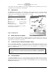
2.4.7 "Swap" Mode
When a normally-open, momentary, push-button switch is connected between pin 10 on the top connector
and aircraft ground, the user can switch between Com 1 and 2 by depressing this switch without having to
turn the mic selector switch. This yoke mounted switch eliminates the need of removing your hands from
the yoke to change transceivers.
NOTICE: Some older model radios may cause the Swap mode to activate on the release of the
PTT switch, due to the excessive back EMF from the collapsing relay coil field. Verify that back
EMF suppression, in the form of a diode across the T/R relay coil, is present if un-commanded
Swap occurs.
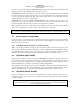
2.4.8 Backlighting
The PMA6000 has an automatic back-lighting system controlled by a photo detector. Additional control
can be gained by the aircraft avionics dimmer control. Connect the dimmer control line to bottom connec-
tor pin D for 14-volt systems, and to bottom connector pin F for 28-volt systems. Pin E is light ground.
This installation provides the ability to bring the backlighting level to zero. If dimmer control is not used, a
constant low-level back light illumination has been established for nighttime viewing. The photocell lo-
cated at the lower right hand side of the unit face will automatically adjust the backlight of the push-button
lamps as well as the rotary mic selector switch light intensity.