
Manual

PM1000-DAP Dual Audio System Intercom Page 10 April 2008
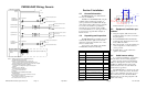
1A
11-33 VDC
14
1
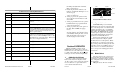
11900D Sub-D DB-25 Male
Copilot Phones Hi
Copilot Phones Lo
19
6
22
21
10
Copilot PTT
Copilot Mic Audio Hi
Mic Audio Lo
Pilot Mic PTT
Pilot Mic Audio Hi
Pilot Mic Audio Lo
15
3
16
2
Power Out (+9VDC)
Expansion Audio In
Expansion Audio Out
Ground
24
23
11
These pins used for expansion modules only
N
O
T
E
S
:
1
.
I
N
T
E
R
C
O
M
S
Y
S
T
E
M
M
U
S
T
B
E
O
R
D
E
R
E
D
S
P
E
C
I
F
I
C
A
L
L
Y
F
O
R
U
S
E
W
I
T
H
D
U
A
L
A
U
D
I
O
S
Y
S
T
E
M
2
.
C
A
U
T
I
O
N
:
T
h
i
s
w
i
r
i
n
g
d
i
a
g
r
a
m
w
a
s
d
r
a
w
n
f
o
r
r
e
f
e
r
e
n
c
e
o
n
l
y
.
Y
o
u
M
U
S
T
v
e
r
i
f
y
p
r
o
p
e
r
o
p
e
r
a
t
i
o
n
u
s
i
n
g
t
h
e
D
u
a
l
A
u
d
i
o
P
a
n
e
l
T
e
s
t
B
o
x
a
v
a
i
l
a
b
l
e
f
r
o
m
P
S
E
n
g
i
n
e
e
r
i
n
g
t
o
d
e
t
e
r
m
i
n
e
t
h
a
t
t
h
e
s
y
s
t
e
m
w
i
l
l
b
e
c
o
m
p
a
t
i
b
l
e
.
3
.
P
S
E
n
g
i
n
e
e
r
i
n
g
D
O
E
S
N
O
T
g
u
a
r
a
n
t
e
e
c
o
m
p
a
t
a
b
i
l
i
t
y
o
r
i
s
r
e
s
p
o
n
s
i
b
l
e
f
o
r
p
r
o
v
i
d
i
n
g
t
e
c
h
n
i
c
a
l
s
u
p
p
o
r
t
f
o
r
d
u
a
l
a
u
d
i
o
p
a
n
e
l
i
n
s
t
a
l
l
a
t
i
o
n
s
.
4
.
A
l
l
w
i
r
e
m
u
s
t
c
o
n
f
o
r
m
t
o
M
I
L
-
2
2
7
5
9
o
r
2
7
5
0
0
.
M
i
n
i
m
u
m
2
4
g
a
g
e
s
h
i
e
l
d
e
d
w
i
r
e
.
5
.
U
s
e
2
-
,
3
-
,
a
n
d
4
-
c
o
n
d
u
c
t
o
r
w
i
t
h
s
h
i
e
l
d
a
s
i
n
d
i
c
a
t
e
d
.
6
.
T
H
I
S
S
Y
S
T
E
M
I
S
N
O
T
C
O
M
P
A
T
A
B
L
E
W
I
T
H
C
E
S
S
N
A
C
I
T
A
T
I
O
N
M
O
D
E
L
S
.
7
.
U
s
e
i
n
s
u
l
a
t
i
o
n
w
a
s
h
e
r
s
a
t
a
l
l
j
a
c
k
s
.
G
r
o
u
n
d
s
h
i
e
l
d
s
a
t
o
n
e
e
n
d
o
n
l
y
.
8
.
T
h
i
s
c
o
n
f
i
g
u
r
a
t
i
o
n
i
s
f
o
r
2
-
p
l
a
c
e
s
o
n
l
y
.
C
o
n
t
a
c
t
t
h
e
f
a
c
t
o
r
y
f
o
r
i
n
f
o
r
m
a
t
i
o
n
o
n
e
x
p
a
n
d
i
n
g
t
h
i
s
s
y
s
t
e
m
.
9
.
N
o
c
o
n
n
e
c
t
i
o
n
t
o
t
h
e
P
T
T
i
s
n
e
c
e
s
s
a
r
y
.
Power In
Ground
18
5
Pilot Phone Audio Hi
Pilot Phone Audio Lo
Power Ground
To Aircraft Pilot Radio Mic Audio Lo
To Aircraft Pilot Radio Mic Audio Hi
To Aircraft Copilot Radio Mic Audio Lo
To Aircraft Copilot Radio Mic Audio Hi
To A/C Pilot Radio Phones Audio Hi
To A/C Copilot Radio Phones Audio Hi
To A/C Pilot Radio Phones Audio Lo
To A/C Copilot Radio Phones Audio Lo
P
S
P
S
Pilot Phones Jack
Copilot Phone Jack
Copilot Mic Jack
Pilot Mic Jack
No Connection
No Connection
PM1000-DAP Wiring, Generic
Revision 5 Page 3 200-191-0000
Section 2 Installation
2.1 General Information
The PM1000-DAP comes with hardware
necessary for installation.
Installation of the PM1000-DAP, using the
available wiring and hardware supplied, re-
quires special avionics installation knowledge
other than described in FAA Advisory Circular
43.13-2. It is the installer's responsibility to
determine the approval basis for this installa-
tion. An FAA From 337, or other approval may
be required. See Appendix B for example of
FAA Form 337.
2.2 Unpacking and inspection
The PM1000-DAP was carefully inspected
mechanically and thoroughly tested electroni-
cally before shipment. It should be free of elec-
trical or cosmetic defect.
Upon receipt, verify that the parts kit P/N
250-003-0001, includes the following:
2.3 Equipment installation pro-
cedures
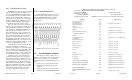
1. Using the template, drill six holes in the
instrument panel in a location convenient to
the pilot positions.
2. Insert the PM1000-DAP from behind the
instrument panel, aligning the holes for the
knobs, LED, and switch.
3. Place the faceplate over the knob shafts and
secure, using the two # 4-40 round head
screws provided.
4. Install the knobs over the volume and
squelch control shafts.
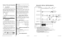
2.4 Cable harness wiring
To complete the installation, a wire harness
must be made as shown in wiring diagrams.
There are many variation of dual ACP in-
stallation. Although there are many successful
installations, PS Engineering cannot supply
technical advice in any case other than as de-
scribed in these appendices.
The PM1000-DAP is connected to the exist-
ing jacks. To connect intercom into the aircraft
audio system, parallel the appropriate set of ca-
bles from the intercom to the Aircraft Radio
Headset Jacks. See the wiring diagram for all
details of the wiring.
Part Number Description Quantity
475-440-0003 #4-40 Machine screws, black 2
625-002-0001 Large inner knobs 2
625-002-0004 Small knobs w pointer 2
425-025-0009 25-pin Sub-D male connector shell 1
625-025-0001 Connector hood 1
575-002-0004 Faceplate, Reversible 1
200-191-0000 Operator's and Installation Manual 1
122-102-0001 Drill Template 1
561-011-0001 Audio Transformers, 200 mW 2
425-020-5089 Sub D pins. Male 25
475-002-0002 Thumbscrews 2
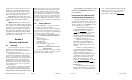
Ø0.125 in
Ø0.265 in
Ø0.375 in
Ø0.25 in
0.838 in
1.2 in
0.5 in
0.32 in
PM1000-DAP Hole spacing (Not to scale)