
User guide

PM1000II Specialty Intercom Manual Page 8 Sept. 2007
4.2 Factory Service
The PM1000II is covered by a one-year limited
warranty. See warranty information.
Call PS Engineering, Inc. at (865) 988-9800
before you return the unit. This will allow the service
technician to provide any other suggestions for
identifying the problem and recommend possible
solutions.
After discussing the problem with the technician
and you obtain a Return Authorization Number,
ship product to:
PS Engineering, Inc.
Attn: Service Department
9800 Martel Road
Lenoir City, TN 37772
(865) 988-9800 FAX (865) 988-6619.
NOTE:
PS Engineering is not responsible for units
shipped US Mail.
If no method of payment is provided, the units
will be returned COD. If no RMA or description of
problem is present, the shipment will be refused.
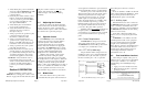
12345
1415161718
6789
19202122
10
2324
1112
25
13
C
o
p
i
l
o
t
I
C
S
K
e
y
B
C
o
p
i
l
o
t
I
C
S
K
e
y
A
P
o
w
e
r
(
1
1
-
3
3
V
D
C
)
G
r
o
u
n
d
P
i
l
o
t
I
C
S
K
e
y
B
P
i
l
o
t
I
C
S
K
e
y
A
A
/
C
R
a
d
i
o
G
r
o
u
n
d
A
/
C
R
a
d
i
o
I
n
p
u
t
P
i
l
o
t
P
h
o
n
e
s
G
n
d
P
i
l
o
t
P
h
o
n
e
s
H
i
C
o
p
i
l
o
t
&
P
a
s
s
P
h
o
n
e
s
L
o
C
o
p
i
l
o
t
&
P
a
s
s
P
h
o
n
e
s
H
M
u
s
i
c
I
n
p
u
t
L
o
M
u
s
i
c
I
n
p
u
t
H
i
P
a
s
s
2
M
i
c
H
i
C
o
p
i
l
o
t
M
i
c
H
i
P
a
s
s
1
M
i
c
H
i
C
o
p
i
l
o
t
P
T
T
C
o
p
i
l
o
t
&
P
a
s
s
M
i
c
L
o
P
i
l
o
t
M
i
c
A
u
d
i
o
H
i
P
i
l
o
t
M
i
c
L
o
P
i
l
o
t
P
T
T
A
/
C
R
a
d
i
o
P
T
T
A
/
C
M
i
c
A
u
d
i
o
H
i
A
/
C
R
a
d
i
o
G
n
d
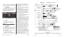
11909 Connector layout, viewed from rear
Sept. 2007 Page 3 200-125-0100
the unit off.
1.4 Approval Basis *None*
The PM1000II, part number 11909 is
NOT FAA Approved. It is the installers
responsibility to determine suitability for use.
1.5 Specifications
Input power: 13.8 - 27.5 Volts DC
Current Drain: < 250 mA (Externally fused at 1 Amp)
Headphone Impedance: 150-1000 ohms typical
Audio Distortion: <10% @ 75 mW into 150 Ω load
Aircraft Radio Impedance: 1000 Ω typical
3 dB Music Frequency Response: 200 Hz to 15 kHz
Unit weight: 12 Ounces (0.342 kg)
Dimensions: 1.25" H x 2.60" W x 5.50" D
(3.2 x 6.6 x 14 cm)
Temperature -20ºC to +55ºC
Altitude 50,000 ft.
1.6 Equipment required but
not supplied
A. Headphones, 150Ω monaural, up to four as
required
B. Microphones, up to four, as required
C. Interconnect wiring
D. Circuit Protection 1 Amp.
1.7 License Requirements
None
Section 2 Installation
2.1 General Information
The PM1000II comes with all necessary
hardware for installation.
Installation of the PM1000II, using the
available wiring and hardware supplied, does
not require special tools or knowledge other
than described in FAA Advisory Circular
43.13-2. It is the installer's responsibility to
determine the approval basis for this installation. .
2.2 Unpacking and inspection
The PM1000II was carefully inspected
mechanically and thoroughly tested electronically
before shipment. It should be free of electrical or
cosmetic defect.
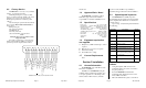
Upon receipt, verify that the parts kit includes
the following:
2.3 Equipment installation pro-
cedures
1. Using the template, drill six holes in the
instrument panel in a location convenient to
the pilot position(s).
2. Insert the PM1000II from behind the
instrument panel, aligning the holes for the
knobs, LED, and switch.
3. Place the aluminum face-plate over the knob
Part Number Description Quantity
475-442-0002 #4-40 Machine screws, black 2
625-002-0001 Concentric inner knobs 2
625-002-0002 Outer knobs w pointer 2
425-025-0095 25 pin Sub-d Shell 1
625-025-0001 Connector hood 1
575-002-0004 Reversible aluminum face plate 1
11910 4-place mono jack kit (incl. phones
and mic jack, insulating washers and
1/8” music jack)
1
200-125-0100 Operator's and Installation Manual WEB
122-102-0001 Drill Template 1
425-020-5089 Male Pins—Crimp 25