9800 Martel Road Lenoir City, TN 37772 www.ps-engineering.com PAR100EX Document P/N 200-760-0000 Revision 12, January 2014 Audio Selector Panel with VHF Communications Transceiver and High-fidelity Stereo Intercom System Installation and Operation Manual Patented under one or more of the following; No.
Table of Contents Section I – GENERAL INFORMATION................................1-1 1.1 1.2 1.3 1.4 1.5 1.6 1.7 1.8 INTRODUCTION...................................................................................................................... 1-1 SCOPE ....................................................................................................................................... 1-1 EQUIPMENT DESCRIPTION ..........................................................................................
PS Engineering Inc. ® PAR100EX Audio Selector Panel and Intercom System Installation and Operator’s Manual 2.15 2.16 2.17 2.18 PAR100EX PIN ASSIGNMENTS ................................................................................................ 2-19 POST INSTALLATION CHECKOUT ............................................................................................. 2-20 UNIT INSTALLATION ................................................................................................................
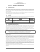
PS Engineering Inc. ® PAR100EX Audio Selector Panel and Intercom System Installation and Operator’s Manual Section I – GENERAL INFORMATION 1.1 INTRODUCTION The PAR100EX represents another evolutionary step in cockpit audio control and intercommunications utility. Using our patented IntelliVox® design and pilot programmable configurations, this marks the next level of audio control. The unit is designed for outstanding ergonomics and visually defined mode annunciation and selection.
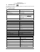
PS Engineering Inc. ® PAR100EX Audio Selector Panel and Intercom System Installation and Operator’s Manual 1.4 APPROVAL BASIS — NONE The PAR100EX is not intended, or approved for installation on US Registered Civilian Aircraft with normal airworthiness certificates. 1.5 SPECIFICATIONS DIMENSIONS: Height: 1.3 in. (3.3 cm) Width: 6.25 in. (16.9 cm) Depth behind panel 7.15 in. (18.16 cm) WEIGHT PAR100EX Unit 1.34 lb. (0.61 kg) Rack with connectors 0.51 lb. (0.
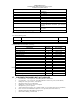
PS Engineering Inc. ® PAR100EX Audio Selector Panel and Intercom System Installation and Operator’s Manual -12dB SINAD @ 0.3µV (1KHz audio with 70% modulation) -70dB 0.5 - 10.0µV RS232 Nominal 4 watts output to 4 ohms Nominal 100 milliwatts output to 600 Ω -20 to +55 degrees Celsius < +/- 4.00 ppm W-3.4” x H-2.5” x D-4.7” (plus 1.5” for harness) W-87mm xH-64mm x D-119mm (plus 35mm for harness) 13.
PS Engineering Inc. ® PAR100EX Audio Selector Panel and Intercom System Installation and Operator’s Manual 1.8 LICENSE REQUIREMENTS In some localities other than the United States, an Aircraft Radio Station license may be required. In the United States, you do not need a license to operate a two-way VHF radio aboard aircraft operating domestically. Aircraft operating domestically do not land in a foreign country or communicate via radio with foreign ground stations.
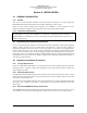
PS Engineering Inc. ® PAR100EX Audio Selector Panel and Intercom System Installation and Operator’s Manual Section II - INSTALLATION 2.1 2.1.1 GENERAL INFORMATION SCOPE This section provides detailed installation and interconnection instructions for the PS Engineering PAR100EX Audio Selector Panel/Intercom/ with VHF communication radio controls. Please read this manual carefully before beginning any installation to prevent damage and postinstallation problems.
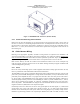
PS Engineering Inc. ® PAR100EX Audio Selector Panel and Intercom System Installation and Operator’s Manual Figure 2-1 M760REM VHF Transceiver (Remote Mount) 2.3.4 Audio Panel Mounting Rack Installation Remove the unit from the mounting tray by unscrewing the 3/32" hex-head screw that is in the center of the unit. Use caution to avoid hitting the photo-detector lens. Carefully slide the unit free of the tray. Set the unit aside in a safe location until needed.
PS Engineering Inc. ® PAR100EX Audio Selector Panel and Intercom System Installation and Operator’s Manual no circumstances combine a microphone and headphone wiring into the same shielded bundle. Always use a 2- or 3-conductor, shield wire as shown on the installation-wiring diagram. The shields can be daisy-chained together, and then connected to the ground lugs mounted on the center of the back plate.
PS Engineering Inc. ® PAR100EX Audio Selector Panel and Intercom System Installation and Operator’s Manual 2.4.4 Communications Push-to-Talk An important part of the installation is the PTT (Push-To-Talk) switches that allow the use of your aircraft communications radio for transmissions. There are three typical configurations that can be used. Select the case that best fits the installation. Only the person who presses their PTT switch will be heard over the radio.
PS Engineering Inc. ® PAR100EX Audio Selector Panel and Intercom System Installation and Operator’s Manual If the M760REM is used as COM 1, the PAR100EX can fail-safe to it, because it is divided internally as audio panel and COM control. In addition, the M760REM power supply is provided by an independent circuit breaker and power supply in the PAR100EX. See § 3.2 for operational information. As shipped from the factory, the PAR100EX is configured to use the M760REM as COM 2.
PS Engineering Inc. ® PAR100EX Audio Selector Panel and Intercom System Installation and Operator’s Manual Step 1 Place nut, washer and gasket over cable and strip jacket to 5/16” (7.9 mm). 3/32” Step 2 Comb out braid and fold out. Trim insulation off center conductor to 3/32” (2.4 mm). Tin center conductor. Step 3 Pull braid wires forward and taper toward center conductor. Place clamp over braid and push back against cable jacket.
PS Engineering Inc. ® PAR100EX Audio Selector Panel and Intercom System Installation and Operator’s Manual 2.6.1 Paring separate music and telephone devices It is possible to use a different music source (iPad, iPod with Bluetooth adapter, Bluetooth enabled laptop, etc) and telephone. However, the music source must be paired first, before the telephone, if the telephone also has music streaming capability. Otherwise, the Smartphone will also take over the music streaming. Only one can be a phone.
PS Engineering Inc. ® PAR100EX Audio Selector Panel and Intercom System Installation and Operator’s Manual NOTE: If the PAR100EX/M760REM is installed in 28V aircraft without properly configuring the unit, the M760REM radio will be damaged. See § 2.9 The LCD display backlighting is controlled by the automatic photocell dimming. In addition, the text inverts for nighttime mode when the ambient light is low.
PS Engineering Inc. ® PAR100EX Audio Selector Panel and Intercom System Installation and Operator’s Manual 2.7.1 Entertainment Inputs The PAR100EX has two INDEPENDENT inputs wired into the rear connectors, in addition to the Bluetooth® music streaming (which is presented as Music 1). Entertainment input number 1 is J2 pins 23 (left channel) and 24 (right channel), with respect to pin 25, and Entertainment number 2 is connected to 26 (left channel), 27 (right channel), with respect to 28.
PS Engineering Inc. ® PAR100EX Audio Selector Panel and Intercom System Installation and Operator’s Manual Long screws Figure 2-4 Screw Location and disassembly Short screw (if present) 2.9 Conversion to 12V electrical system. As shipped from PS Engineering, the PAR100EX is configured to operate in 24 aircraft. This protects the M760REM from damage if installed in 24 volt aircraft. If operation in a 12-volt aircraft is desired, internal jumpers must be changed to allow operation of the M760REM.
PS Engineering Inc. ® PAR100EX Audio Selector Panel and Intercom System Installation and Operator’s Manual Jumpers in 24V location Figure #2 200-760-0000 Page 2-11 Rev. 12, Jan.
PS Engineering Inc. ® PAR100EX Audio Selector Panel and Intercom System Installation and Operator’s Manual 2. Relocate the red jumpers so it matches the picture below. Jumpers set for 12 V Operation Jumpers set for 24V operation Jumpers set for 12V operation Jumpers set for 24V operation 2.10 Adjustments The PAR100EX is factory adjusted to accommodate the typical requirements for most aircraft configurations. There are three adjustments accessible through the top cover (see §2.
PS Engineering Inc. ® PAR100EX Audio Selector Panel and Intercom System Installation and Operator’s Manual TEL VOL- The received telephone volume. The unit is set at the factory for 75% of volume. Turn Clockwise to increase the TEL receive volume. LCD CST: adjusts display contrast to suit individual preferences and ambient light. TEL VOL Unswitched 3 LCD Contrast 3 Figure 2-5 PAR100EX Cover adjustment locations 2.
PS Engineering Inc. ® PAR100EX Audio Selector Panel and Intercom System Installation and Operator’s Manual NOTE: If top cover is removed for ANY reason, you MUST replace the cover screws with the proper length, otherwise damage will result. DIP Switches Shorter Screw Figure 2-6 – PAR100EX DIP Switches OFF OFF ON ON 1 2 3 4 5 6 Figure 2-7 DIP switches Change the settings as shown in the table below.
PS Engineering Inc. ® PAR100EX Audio Selector Panel and Intercom System Installation and Operator’s Manual Carefully reassemble the unit. 2.12 Reassembly 3. Using the nylon spacer removed in step 2, compress the spacer so it becomes oblong. Figure #3 a. Install one long screw through the top lid, near the front edge on the power supply board side, and add then add the nylon spacer from § 2.8. Figure #4 4. Place the lid back on the unit aligning holes. 5. Install qty.
PS Engineering Inc. ® PAR100EX Audio Selector Panel and Intercom System Installation and Operator’s Manual 6. Install qty. 1 short thread screw to the rear of the unit. 2.13 Communications Antenna Installation Notes 2.13.1 Metal Skin Aircraft For metal skin aircraft a ¼ wave whip is the easiest antenna to fit. Ensure that the antenna base and the coax shield are firmly grounded to the skin of the airframe, on the inside of the aircraft.
PS Engineering Inc. ® PAR100EX Audio Selector Panel and Intercom System Installation and Operator’s Manual Beware of fabric surfaces with silver dope finishes. The silver dope is a conductive surface, and will screen antennas which are mounted internally. Refer to the Microair Avionics website www.microair.com.au for more detail on antennas suitable for non-metal skin aircraft. 2.13.
PS Engineering Inc. ® PAR100EX Audio Selector Panel and Intercom System Installation and Operator’s Manual Figure 2-10 Radio Output Level Adjustment 2.14.1 Installation of Ferrite Core Suppressor. The RFI suppressor must be installed on the audio/data cable as shown to prevent RFI. These devices are fitted over wiring harnesses to “attenuate” the RF noise signals passing along the wires. Symptoms may include: 1. Squelch light stays illuminated (without any transmit or receive). 2.
PS Engineering Inc. ® PAR100EX Audio Selector Panel and Intercom System Installation and Operator’s Manual 2.
PS Engineering Inc. ® PAR100EX Audio Selector Panel and Intercom System Installation and Operator’s Manual 2.16 Post Installation Checkout After wiring is complete, verify power is ONLY on pins 8, 9 and 44 of the J2 and airframe ground on connector pins 10, 11 and 43. Failure to do so will cause serious internal damage and void PS Engineering's warranty. 2.17 Unit Installation To install the PAR100EX, gently slide the unit into the mounting rack until the hold-down screw is engaged.
PS Engineering Inc. ® PAR100EX Audio Selector Panel and Intercom System Installation and Operator’s Manual 2.18.1 M760REM Checkout 2.18.1.1 Ground check: 1. Connect an in-line type watt meter and verify that the antenna VSWR does not exceed 2:1 across the frequency band from 118.000 to 137.975 MHz. 2. Select the frequency of a local communications facility and verify that the receiver output is clear and intelligible. 3.
PS Engineering Inc. ® PAR100EX Audio Selector Panel and Intercom System Installation and Operator’s Manual Section III OPERATION 3.1 SCOPE This section provides detailed operating instructions for the PS Engineering PAR100EX, Audio Selector Panel/Intercom/VHF Communication Control Systems. Please read it carefully before using the equipment so that you can take full advantage of its capabilities. This section is divided into sections covering the basic operating areas of the PAR100EX systems.
PS Engineering Inc. ® PAR100EX Audio Selector Panel and Intercom System Installation and Operator’s Manual separately in the event of a problem in the audio panel portion, or audio panel power.
PS Engineering Inc. ® PAR100EX Audio Selector Panel and Intercom System Installation and Operator’s Manual Navigation aid audio push buttons are labeled A1, A2. The MKR (Marker), ADF AUX (auxiliary) and DME audio is available is interfaced through an unswitched input. 3.6 VHF Transceiver control (5) The right side of the PAR100EX is dedicated to control of the VHF communications transceiver. Frequency selection is always directed to the STANDBY side of the display. 3.6.
PS Engineering Inc. ® PAR100EX Audio Selector Panel and Intercom System Installation and Operator’s Manual When MON is active, the receiver is tuned to the Standby frequency and passes received audio on that channel. When the Active frequency receives a signal, the signal from the active frequency is automatically provided to the audio. Both active and standby frequencies are monitored at the same time for a signal. A signal can be received on either the active or the standby frequency.
PS Engineering Inc. ® PAR100EX Audio Selector Panel and Intercom System Installation and Operator’s Manual Manufacturer Pilot Model 11-20 & 11-90 Mic Muff™ Part Number 90015 Sennheiser Telex 90015 Airman 750, Echelon AIR3000 90015 90010 3.7.1.1 3.7.2 Mono headsets in Stereo Installation The pilot and copilot positions work with stereo or mono headsets. All passenger headsets are connected in parallel.
PS Engineering Inc. ® PAR100EX Audio Selector Panel and Intercom System Installation and Operator’s Manual 3.8.2 Telephone (TEL) Operation When the Bluetooth-enabled phone receives an incoming call, the PAR100EX will play a ring tone. Answer the call from your telephone handset. The PAR100EX exits the telephone mode automatically when the cellular phone hangs up. In TELEPHONE mode, the pilot microphone and headphones are connected to the cell phone.
PS Engineering Inc. ® PAR100EX Audio Selector Panel and Intercom System Installation and Operator’s Manual NOTE: All music devices should be turned off for take off, landing, or any critical phase of flight. FAA Regulation 14 CFR 91.21 restricts the use of portable electronic devices. §91.21 “(a) Except as provided in paragraph (b) of this section, no person may operate, nor may any operator or pilot in command of an aircraft allow the operation of, any portable electronic device on any of the following U.
PS Engineering Inc. ® PAR100EX Audio Selector Panel and Intercom System Installation and Operator’s Manual Section IV – Warranty and Service 4.1 Warranty In order for the factory warranty to be valid, the installations must be accomplished under the supervision of an authorized PS Engineering dealer. If the unit is being installed by a non-certified individual in an experimental aircraft, a PS Engineering authorized dealer, or factory-made intercom harness must be used for the warranty to be valid.
PS Engineering Inc. ® PAR100EX Audio Selector Panel and Intercom System Installation and Operator’s Manual Appendix A – External PTT Hook Up Part of the installation includes the installation of PTT (Push To Talk) switches that allow the use of your aircraft radio for communications transmissions. There are three possible configurations ; you must select the case that best fits your installation. NOTE: Only the person who presses their PTT switch will be heard over the radio.
PS Engineering Inc. ® PAR100EX Audio Selector Panel and Intercom System Installation and Operator’s Manual Appendix B – PAR100EX Installation Drawings Ground Lug 475-440-0001 (x2) J2 J1 1 15 30 16 31 44 Back plate assy 1 15 30 475-440-0001 (x2) Screw w/washer 16 31 44 475-009-0001 ground lug (x2) Viewed from Back Ground Lug Ground lug detail Rear plate detail (not to scale) 6.31in 1.28in 1.28 in 0.96 in 0.36 in 0.37 in 3.87 in 5.53 in 6.
PS Engineering Inc. ® PAR100EX Audio Selector Panel and Intercom System Installation and Operator’s Manual M760REM Radio Installation Drawings 3.70 in 3.40 in 2.99 in .160 x .400 in 4 places 4.60 in 200-760-0000 Appendix B Rev. 12, Jan.
PS Engineering Inc.
PS Engineering Inc. ® PAR100EX Audio Selector Panel and Intercom System Installation and Operator’s Manual Appendix D – J2 Connector Interconnect PAR100EX J2 CONNECTOR (Sub-D 44-pin male on tray) 31 16 1 Pilot Phones (R) Pilot PhonesJack Pilot Phones (L) Pilot Phones Lo 4 3 2 Copilot Phones (R) Copilot PhonesJack Copilot Phones (L) Copilot Phones Lo Communications Transceiver (R760) Unswitched Input #4 Hi Unswitched Audio #4 Unswitched Audio Lo Pass. Mic Hi Pass. 1 Mic Jack Pass.