9800 Martel Road Lenoir City, TN 37772 PAV80 High-fidelity Audio-Video In-Flight Entertainment System With DVD/MP3/CD Player and Radio Receiver STC-PMA Document P/N 200-800-0101 Revision 6 September 2005 Installation and Operation Manual Warranty is not valid unless this product is installed by an Authorized PS Engineering dealer or if a PS Engineering harness is purchased. PS Engineering, Inc.
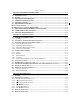
Table of Contents SECTION I GENERAL INFORMATION........................................................................ 1-1 1.1 INTRODUCTION........................................................................................................... 1-1 1.2 SCOPE ............................................................................................................................. 1-1 1.3 EQUIPMENT DESCRIPTION ..................................................................................... 1-1 1.
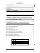
PS Engineering PAV80 Series IFE System Installation and Operator’s Manual 3.5 3.6 DISPLAY DIMMING (7) ..................................................................................................... 3-5 ERROR CODES .................................................................................................................. 3-5 SECTION IV- WARRANTY AND SERVICE.................................................................. 4-1 4.1 4.2 WARRANTY .................................................
PS Engineering PAV80 Series IFE System Installation and Operator’s Manual Section I GENERAL INFORMATION 1.1 INTRODUCTION Quality cockpit and cabin entertainment has long been an elusive dream in general aviation. From marginal performance to unapproved parts, pilots couldn’t enjoy the same entertainment in their aircraft as they could in the family car. The PAV80-Series represents such a product.
PS Engineering PAV80 Series IFE System Installation and Operator’s Manual Operation is subject to the following conditions: This device may not cause harmful interference. This device must accept any interference received, including interference that may cause undesired operation. 1.
PS Engineering PAV80 Series IFE System Installation and Operator’s Manual PVT801 Video Terminal Unit FAA-TSO COMPLIANCE APPLICABLE DOCUMENTS: SAE AS8034 RTCA/DO-160D RTCA/DO-178B (Level E) RTCA DO-254 (Level E) ENVIRONMENTAL Qualifications: B4BABSXXXXXXZBBBAUHXXX Temperature Range: Operating: -0º C to 40ºC Storage: -20º C to 85ºC Altitude: Up to 25,000 feet in a non-pressurized area of the cockpit. 5.98” W x 4.28” H X 1.20” D DIMENSIONS: (152x 108 x 30.5mm) Screen size 5.
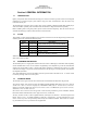
PS Engineering PAV80 Series IFE System Installation and Operator’s Manual Model Part Number 050-800-0100 050-801-0100 051-803-0150 PAV80 PVT801 Remote Description DVD-IFE System with AM/FM CD MP3 LCD Video Display, 5.
PS Engineering PAV80 Series IFE System Installation and Operator’s Manual 1.8 APPROVED AUDIO SYSTEMS This is a list of audio system that the PAV80 should interface with adequately. Approved Audio Systems, PAV80 Certified interface is approved only for audio systems that are FAA-TSO approved.
PS Engineering PAV80 Series IFE System Installation and Operator’s Manual Section II - Installation 2.1 GENERAL INFORMATION 2.1.1 SCOPE These sections provide detailed installation and interconnect instructions for the PAV80 In-Flight Entertainment System with integrated Digital Versatile Disc (DVD) Player and AM/FM radio receiver. Please read this manual carefully before beginning any installation to prevent damage and post-installation problems.
PS Engineering PAV80 Series IFE System Installation and Operator’s Manual 2.3.3 Mounting Rack Installation Remove the unit from the mounting tray by unscrewing the 3/32" hex-head screw that is near the left edge of the unit. Carefully slide the unit free of the tray. Set the unit aside in a safe location until needed. Install the tray using six FHP 6-32 x ½" screws. The unit must be supported at front and rear of the mounting tray. See Appendix B. 6.31” 2.
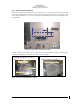
PS Engineering PAV80 Series IFE System Installation and Operator’s Manual Panel Opening Saw and file used to remove existing instrument panel from this location Figure 2-3 Completed panel opening (Typical) Figure 2-4 Completed panel installation 2.3.4 Connector Assembly The unit connector mates directly with the circuit boards in the PAV80. The connector (part number 120425-4402 is a Molex crimp-type, and requires the use of a Molex hand crimp tool, EDP P/N 11-01-0203, CR6115B (or equiv.).
PS Engineering PAV80 Series IFE System Installation and Operator’s Manual Front of tray Washer 475-632-0001 Nut 475-632-0005 475-632-0007 Screw (x2) A 475-440-0007 (2 plcs) Screws Rear of tray 120-425-4402 Connector C B 430-730-0025 Tray Shield Figure 2-5 -Tray Assembly 2.4 Cable Harness Wiring Referring to the wiring diagrams contained in the Appendix, assemble a wiring harness as required for the installation. All wires must be MIL-SPEC in accordance with current regulations.
PS Engineering PAV80 Series IFE System Installation and Operator’s Manual 2.4.2 Power The PAV80-Series units are compatible with both 14 and 28 Volt DC systems. A five (5) Amp PULL-TYPE breaker is required. Power and ground wires must be a twisted #18 AWG pair. Connect airframe power ground to Pin 22 only. If the Video Distribution Amplifier (PVA802) is used, a second circuit breaker (5 A) must be installed. Power must be connected to the P802, pin 13 only. NOTE: The PVA80 can power ONE (1) PVT801.
PS Engineering PAV80 Series IFE System Installation and Operator’s Manual 2.4.5 Aux Entertainment Audio and AUX Enable Besides the disc and AM/FM, the PAV80 has the ability to act as a switching control for an additional entertainment input, both audio and video. The audio input is Pin 7 (R), Pin H (L) with respect to Pin F (ground). The video input is Pin 17 (with respect to Pin U) 2.
PS Engineering PAV80 Series IFE System Installation and Operator’s Manual Connect the PVA802 to a 5-amp PULL TYPE circuit breaker. The unit connector is a crimp type, however, we recommend soldering the small conductors from the RG179 coax. NOTE: This unit can become warm when fully loaded, and should not be mounted where an occupant may have inadvertent contact with it. The PVA802 should be mounted in accordance with AC43.
PS Engineering PAV80 Series IFE System Installation and Operator’s Manual b. c. d. 9. 10. 11. 12. 13. Evaluate the audio performance Evaluate the audio level to verify that the music is adequate under flight conditions. Evaluate the muting system to demonstrate that the music will be adequately muted if desired, by radio and intercom. e. Evaluate the muting override control if equipped. Evaluate failure remediation from crewmember location a. Turn unit off b. Locate and pull unit circuit breaker c.
PS Engineering PAV80 Installation and Operator’s Manual Section III OPERATION GENERAL INFORMATION 3.1 SCOPE This section describes the operation of the PAV80 In-Flight Entertainment system. Operating controls consist of two rotary knobs with push-push switches, and four buttons. Figure 3-1 Front Panel Controls 3.2 Operating Controls The single-disk player is designed for simple operation. The Disc player will begin to play automatically when a MUSIC Disc is inserted.
PS Engineering PAV80 Installation and Operator’s Manual 3.2.4 The ►► Button (4) In disc mode, a short press of this button will advance to the next track. A longer press will put the disc into fast forward mode. Press the play/pause button to resume normal play In AM/FM mode, this button scans up the frequency band. 3.2.5 The Mode Knob (5) In the Disc mode, the knob will advance (CW) or decrease (CCW) the track. In AM or FM radio mode, this knob can be used to tune the radio directly.
PS Engineering PAV80 Installation and Operator’s Manual Table 1-PAV80 Functions Action Disc Result Radio Result ▲ short press Stop ▲ long press Eject (also in AUX) ► short press Play / Pause ►► short press Next track ►► long press Fast forward Increase frequency ◄◄ short press Previous track Decrease frequency ◄◄ long press Rewind Decrease frequency DATA knob CW Select next track Increase radio frequency DATA knob CCW Select previous track Decrease radio frequency DATA knob Push
NOT FOR PILOT VIEWING PS Engineering PAV80 Installation and Operator’s Manual 3.4 Remote Operation The remote supplied is used to control various functions of the secondary audio output.
PS Engineering PAV80 Installation and Operator’s Manual 3.5 Display Dimming The display can be adjusted for ambient light conditions by the connection to the aircraft dimmer bus. At minimum bus voltage (or no lighting present) the display is set at maximum. 3.6 Error Codes The PAV80 has some limited codes used for troubleshooting.
PS Engineering PAV80 Installation and Operator’s Manual Section IV- Warranty and Service 4.1 Warranty In order for the factory warranty to be valid, the installations in a certified aircraft must be accomplished by an FAA-certified avionics shop and authorized PS Engineering dealer. If the unit is being installed by a non-certified individual in an experimental aircraft, a factory-made harness must be used for the warranty to be valid. PS Engineering, Inc.
PS Engineering PAV80 Installation and Operator’s Manual Appendix A – MP3 Creation 5.1 Creating MP3s from an Audio CD 1. 2. 3. 4. 5. 6. 7. Start MusicMatch JukeBox.(www.musicmatch.com) Press the recorder button, which is the small red dot located in the top right corner. This will open the recorder window located at the bottom of the screen. Insert an audio CD into the CD drive. MusicMatch will automatically read the disc and display the contents in the recorder window.
200-800-0101 PIPER PN 101271-013 COPILOT'S PANEL ASSY.
PS Engineering PAV80 Installation and Operator’s Manual FS 76.
PS Engineering PAV80 Installation and Operator’s Manual 6.25 1.97 Existing Avionics Mounting Rails (see detail A) Detail A A A B&C A B&C #6-32 Screws 475-632-0012 (6 plcs) Clipnuts 475-630-0002 (6 plcs) Front of tray 475-440-0007 (2 plcs) Screws A C B 0.92 in 0.32 in 475-632-0007 (2 plcs) Screws Rear of tray 120-425-4402 Connector Washer 475-632-0001 & Nut 475-632-0005 0.32 in Tray Shield 5.57 in 7.
PS Engineering PAV80 Installation and Operator’s Manual PVT801 Display Interface View from solder cup 1= Video Ground 2= Display Power 3= Power Ground 4= Video Signal 3 1 5= No Connection 4 5 2 Figure 6-4 Display connector layout 1.20 in 5.98 in 2.99 in 1.00 in BACK LEFT Connector Exit 4.28 in 3.03 in 1.38 in Mounting Slot 0.2 in 0.25 in Figure 6-5 - PVT801 Monitor Dimension Details 200-800-0101 Appendix B Rev. 6 Sept.
PS Engineering PAV80 Installation and Operator’s Manual VIEWED FROM REAR Ø0.185 in (4 plcs) 5.10 3.40 4.5 in Cable Exit 5.13 in 1.76 in 0.9 in 0.57 in 6.1 in 6.83 in Figure 6-6 PVT801 Mounting Tray Dimensions (if used) Figure 6-7 Portable bracket drawing (430-800-1362, not to scale) 200-800-0101 Appendix B Rev. 6 Sept.
200-800-0101 19 5 70 18 2 1 20 3 3 21 5 4 Appendix B 23 6 Breaker Added was ADF 22 3 5 24 7 25 5 8 27 5 5 10 IFE 9 5 28 11 29 12 5 VID DIS 5 13 APPROVAL: CHECKED BY: RSH NAME GLP ACTIVITY NEW RELEASE DRAWN BY: MATERIAL REV 0 5 31 5 14 DATE 07-09-03 07-09-03 A SCALE SIZE TITLE 5 34 5 17 ----- ----- ECO NONE CAGE CODE 120-800-8802 DRAWING NUMBER IFE Breaker Location ENGINEERING INCORPORATED REVISIONS 5 5 DESCRIPTION 33 7.
N/C N/C Video Input Signal Video Input Low Display 4 Power Video Output Lo # 4 Video Output Display 3 Power ground Display 3 Power Video Output Lo #2 Video Output Display 2 Power ground Display 2 Power Video Output Lo #3 Video Output Display 1 Power ground Display 1 Power Video Output Lo #1 Video Output Remote ON N/C Display 4 Power ground Power (11-33 VDC) A/C Power ground Power (11-33 VDC) PS Engineering PAV80 Installation and Operator’s Manual 5.470 Ø0.136 (4 plcs) 4.000 200-800-0101 3.500 4.
PS Engineering PAV80 Installation and Operator’s Manual Appendix C Connector Interconnect 7.
200-800-0101 Antenna Input Antenna Ground 17 U 18 V AUX Video Composite Input Hi AUX Video Composite Input L0 Appendix C Remote Ground 14- 28 VDC Aircraft Power (5 A Breaker) Video Composite Output Hi Video Composite Output Lo Remote ON NOTE 4 24 AWG minumum.. 2. Power and Ground #18AWG Mil-Spec Tefzel minimum. Lighting #22 AWG minimum. 3. Circuit breaker must be PULL TYPE 4. Video cables must be RG-179/U MIL-C17 5.
PS Engineering PAV80 Installation and Operator’s Manual Appendix D- STC information and instructions for continuing airworthiness 8.1 Instructions for FAA Form 337, PAV80s The STC was developed using an Approved Model List (AML). One method of airworthiness approval is through an FAA Form 337, Major Repair and Alteration (Airframe, Powerplant, Propeller, or Appliance) In the case of the PAV80, you may use the following text as a guide.
PS Engineering PAV80 Installation and Operator’s Manual 8.3 Master Drawing List The following drawings are contained on the FAA-Approved Master Drawing List, Document Number 002-800-1000: Title Installation Manual Installation Wiring Tray Installation Drawing PAV80 Installation Diagram PAV80 Panel Location PAV80 Breaker Location Multiple Display Wiring PVA802 Dist. Amp Installation Users Guide Flight Manual Supplement * or later revision 8.
PS Engineering PAV80 Installation and Operator’s Manual 200-800-0101 Appendix D Rev. 6, Sept.
PS Engineering PAV80 Installation and Operator’s Manual Appendix E RTCA DO160D/EUROCAE ED-14D Environmental Qualification Form Part Number: 050-800-(-xxx) Manufacturer: PS Engineering Incorporated 9800 Martel Road Conditions Temperature and Altitude Low Temperature High Temperature In-flight Loss of Cooling Altitude Decompression Overpressure Temperature variation Humidity Shock Operational Crash Safety Vibration Explosion Waterproofness Fluids Susceptibility Sand and Dust Fungus Salt Spray Magnetic Effec