9800 Martel Road Lenoir City, TN 37772 www.ps-engineering.com PAC24 Audio Control Panel and Intercom System Installation and Operation Manual FAA-Approved TSO C50c JAA-Approved JTSO C50c Document P/N 200-240-0010 Revision 25, Feb. 2015 In certified aircraft, warranty is not valid unless this product is installed by an Authorized PS Engineering dealer. PS Engineering, Inc.
Table of Contents SECTION I GENERAL INFORMATION ......................................................................................................... 1-1 1.1 INTRODUCTION ............................................................................................................................................ 1-1 1.2 SCOPE............................................................................................................................................................... 1-1 1.
PS Engineering PAC24 Series Audio Selector Panel and Intercom System Installation and Operator’s Manual 3.6.1 SPLIT MODE, SINGLE PANEL ............................................................................................................................. 3-3 3.6.2 SPLIT MODE, DUAL PANEL ............................................................................................................................... 3-4 3.6.3 SPLIT MODE, OBSERVER PANEL (-04XX).............................................
PS Engineering PAC24 Series Audio Selector Panel and Intercom System Installation and Operator’s Manual Section I GENERAL INFORMATION 1.1 INTRODUCTION The PAC24 represents the finest in high-performance cockpit audio control and intercommunications. Using proprietary IntelliVox® design, this unit eliminates the requirements for intercom squelch adjustments. The unit is designed for outstanding ergonomics and visually defined mode annunciation and selection.
PS Engineering PAC24 Series Audio Selector Panel and Intercom System Installation and Operator’s Manual A fail-safe mode connects the pilot headphone and microphone to COM 1 if power is removed for any reason, or if the power switch is placed in the Off (Fail-safe) position. A voice activated (VOX) intercom is included in the PAC24. This system has PS Engineering’s exclusive IntelliVox® circuitry that eliminates manual adjustments.
PS Engineering PAC24 Series Audio Selector Panel and Intercom System Installation and Operator’s Manual Specifications, Continued. POWER REQUIREMENTS (Including Internal Lighting): Voltage: 11 to 33 VDC Maximum Current: 2.5 Amp (Externally protected by a 3 Amp circuit breaker.) Typical operating current: Speaker off: 350 mA Speaker on, 28V, full radio volume 1.5 A Audio Selector Specifications Audio selector panel input impedance: 510 Input Isolation: -60 dB (min.) Speaker Muting: -60 dB (min.
PS Engineering PAC24 Series Audio Selector Panel and Intercom System Installation and Operator’s Manual PAC24 Installation Kit: 250-240-0001 Description 1.7 a) b) c) d) e) f) g) h) 1.
PS Engineering PAC24 Series Audio Selector Panel and Intercom System Installation and Operator’s Manual Section II - Installation 2.1 GENERAL INFORMATION 2.1.1 SCOPE This section provides detailed installation and interconnect instructions for the PS Engineering PAC24Series Audio Control Panel/Intercom System. Please read this manual carefully before beginning any installation to prevent damage and post-installation problems. Installation of this equipment requires special tools and knowledge.
PS Engineering PAC24 Series Audio Selector Panel and Intercom System Installation and Operator’s Manual DIP Switches 4 3 2 1 4 3 2 1 S4 S3 4 3 2 1 4 S2 3 2 1 S5 Figure 2-1 DIP Switch locations 200-240-0010 Page 2-2 Rev. 25, Feb.
PS Engineering PAC24 Series Audio Selector Panel and Intercom System Installation and Operator’s Manual PAC24 Rear Connector S2 1 CVR Audio 2 2 Playback 3 Pass 3 a 4 Expansion power S3 1 Pass 1 Mic 22 2 Expansion in 3 Pass 2 Mic 23 4 Expansion out S4 1 14V light Hi 18 2 Swap 3 28V light hi U 4 Swap +5 S5 1 Expansion Active 2 Dual System 3 Logic Copilot Unit 4 TEL/Duplex Figure 2-2 DIP switches shown schematically 2.3.2.
PS Engineering PAC24 Series Audio Selector Panel and Intercom System Installation and Operator’s Manual Pin 1 J5 J4 Figure 2-3 Pilot/Copilot panel Jumper Location Switch S5 2 OFF 3 OFF Single PAC24 Installation ON Pilot unit –Dual Installation OFF ON Copilot unit – Dual Installation ON Table 2-1 Pilot/Copilot Dual Panel Selection Switch (S5) 2.3.2.
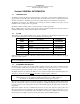
PS Engineering PAC24 Series Audio Selector Panel and Intercom System Installation and Operator’s Manual 2.3.2.4 Pass 2 / Expansion - J3, pin 23 configuration (S3) Switch 3 4 2.3.2.5 S3 ON OFF OFF Expansion audio output Pass 2 mic input ON CVR / IRS Control – J3, pin 2 configuration (S2 PAC24 units can be equipped with an optional Intercom Recording System (IRS, P/N –0200, -0401), which will store up to 60 seconds of radio traffic (on the transceiver selected for transmit).
PS Engineering PAC24 Series Audio Selector Panel and Intercom System Installation and Operator’s Manual 14 V Aircraft 2.3.2.9 28 V aircraft Pin 18= 14 V input Pin 18=Swap Pin U=Swap Pin U =28 V input Expansion Mode / Telephone configuration (S5) Switch S5 1 On Expansion Unit Present (11606 installed) 4 On Duplex Telephone mode for Com 5 NOTE: Set both audio panels the same in a dual installation 2.3.2.
PS Engineering PAC24 Series Audio Selector Panel and Intercom System Installation and Operator’s Manual Dual PAC24 - Pilot Panel- 28 Volt Aircraft 1 2 3 4 SW2 ON OFF ON OFF SW3 ON OFF ON OFF SW4 OFF ON ON OFF SW5 OFF ON OFF See notes Dual PAC24- Copilot Panel- 28 Volt Aircraft 1 2 3 4 SW2 ON OFF ON OFF J4- On/ J5- Pins 1 & 2 SW3 ON OFF ON OFF SW4 OFF ON ON OFF SW5 OFF ON ON See notes J4- Off J5- Pins 2 & 3 Table 2-3 Dual Audio Panel DIP Switch Settings without expansion Dual PAC24 with Expans
PS Engineering PAC24 Series Audio Selector Panel and Intercom System Installation and Operator’s Manual 2.3.4 Mounting Requirements The PAC24 must be rigidly mounted to the instrument panel of the aircraft structure and within view and reach of the pilot position(s). Installation must comply with FAA Advisory Circular AC 43.13-2A. The unit may be mounted in any area where adequate clearance for the unit and associated wiring bundle exist.
PS Engineering PAC24 Series Audio Selector Panel and Intercom System Installation and Operator’s Manual Radiated signals can be a factor when low level microphone signals are "bundled" with current carrying power wires. Keep these cables physically separated. It is very important that you use insulated washers to isolate the ground return path from the airframe to all headphone and microphone jacks.
PS Engineering PAC24 Series Audio Selector Panel and Intercom System Installation and Operator’s Manual Some avionics do not provide a separate audio low, and may introduce additional electrical noise into the system. For best results, connect the audio low from the audio panel to the radio ground, using one conductor of the twisted-shielded cable. 2.4.6 Transmit Interlock Some communications transceivers use a transmit-interlock system.
PS Engineering PAC24 Series Audio Selector Panel and Intercom System Installation and Operator’s Manual 2.4.12.1 Push to talk intercom The PAC24 can be used as an IntelliVox® intercom, or, as a keyed intercom. Switching J3 pin W to ground will inhibit the IntelliVox® and the intercom squelch will not open until the ICS PTT switch is activated. The following pins are used to control the intercom when PTT ICS is desired.
PS Engineering PAC24 Series Audio Selector Panel and Intercom System Installation and Operator’s Manual 2.4.14.1 Standard Versions, -0100 (J3, Pins 22, 23 and a) Interface to the IntelliPAX (111606) expansion unit is through, pins 22 (audio input from expansion unit), 23 (audio output to expansion unit) and a (9 VDC expansion power). These pins are shared with the microphone inputs; therefore the internal DIP switched must be correctly configured (see above). 2.4.14.
PS Engineering PAC24 Series Audio Selector Panel and Intercom System Installation and Operator’s Manual Itisprobable that radio interference will occur in the split mode when the frequencies of the two aircraft radios are adjacent, and/or the antennas are physically close together. PS Engineering makes no expressed or implied warranties regarding the suitability of the PAC24 in Dual or Split Mode. 2.
PS Engineering PAC24 Series Audio Selector Panel and Intercom System Installation and Operator’s Manual 2.
PS Engineering PAC24 Series Audio Selector Panel and Intercom System Installation and Operator’s Manual 2.9 Post Installation Checkout After wiring is complete, verify power is ONLY on pin 25 of the J3 and airframe ground on bottom connector pin A. Failure to do so will cause serious internal damage and void PS Engineering's warranty. 2.10 Unit Installation To install the PAC24, gently slide the unit into the mounting rack until the hold-down screw is engaged.
PS Engineering PAC24 Series Audio Selector Panel and Intercom System Installation and Operator’s Manual 2.11 Internal Recorder Checkout (Optional units only, -0200 and -0400) With headset plugged into pilot’s side jacks, tune COM 1 to local frequency, such as FSS or ATC ground. Select Com 1 on mic selector switch, and record at least five incoming radio transmissions.
PS Engineering PAC24 Series Audio Selector Panel and Intercom System Installation and Operator’s Manual Section III OPERATION GENERAL INFORMATION 3.1 SCOPE This section provides detailed operating instructions for the PS Engineering PAC24 High Performance Audio Selector Panel/Intercom Systems. Please read it carefully before using the equipment so that you can take full advantage of its capabilities. This section is divided into three sections covering the basic operating areas of the PAC24 systems.
PS Engineering PAC24 Series Audio Selector Panel and Intercom System Installation and Operator’s Manual problem. 3.4 Communications Selection (2) There are 10 pushbuttons associated with the communications transceivers. The lower buttons control which transceiver is selected for transmit. The PAC24 gives priority to the pilot’s PTT. If the copilot it transmitting, and the pilot presses his PTT, the pilot’s microphone will be heard over the selected com transmitter.
PS Engineering PAC24 Series Audio Selector Panel and Intercom System Installation and Operator’s Manual 3.5 Receive Audio Selector (1) Receiver audio is selected through 9 momentary push-button, backlit switches. Because the microphone pushbutton selector switch controls what transceiver is being heard, you will always hear the audio from the transceiver that is selected for transmit. The users can identify which receivers are selected by noting which of the green switch LEDs are illuminated.
PS Engineering PAC24 Series Audio Selector Panel and Intercom System Installation and Operator’s Manual 3.6.2 Split Mode, Dual Panel In a dual panel installation, both pilots have access to any combination of transceivers. Because there is cross communication, each PAC24 knows the other unit’s transmitter selection. The audio panel designated as “Pilot’s” will have transmission priority over the panel designated as copilot’s, when both panels are keyed for transmit on the same radio.
PS Engineering PAC24 Series Audio Selector Panel and Intercom System Installation and Operator’s Manual For optimum microphone performance, PS Engineering recommends installation of a Microphone Muff Kit from Oregon Aero (1-800-888-6910). This will not only optimize VOX performance, but will improve the overall clarity of all your communications. Table 3-1 Mic Muff ™ Part Numbers Manufacturer Bose David Clark Lightspeed Peltor Pilot Model Dynamic Electret M87 Dynamic H10-30 H10-20, H10-40 H10-13.
PS Engineering PAC24 Series Audio Selector Panel and Intercom System Installation and Operator’s Manual 3.7.3.2 Dual Installation Intercom Modes ISO: (Up Position): The primary pilot connected to the PAC24 is isolated from the intercom and is connected only to the aircraft radio system. He will hear the selected aircraft radio reception (and sidetone during radio transmissions).
PS Engineering PAC24 Series Audio Selector Panel and Intercom System Installation and Operator’s Manual In a standard dual installation, the pilot and copilot can select TEL (Com 5) mode independently by pressing their respective COM5 Xmt button. The passengers are on the phone only when the pilot has selected Com 5 mode and his ICS mode switch is in the ALL position. The copilot cannot put the passengers on the phone, and the passengers can only get on the phone when the pilot is on the phone.
PS Engineering PAC24 Series Audio Selector Panel and Intercom System Installation and Operator’s Manual Section IV- Warranty and Service 4.1 Warranty In order for the factory warranty to be valid, the installations in a certified aircraft must be accomplished by an FAA-certified avionics shop and authorized PS Engineering dealer. If the unit is being installed by a non-certified individual in an experimental aircraft, a factory-made harness must be used for the warranty to be valid. PS Engineering, Inc.
PS Engineering PAC24 Series Audio Selector Panel and Intercom System Installation and Operator’s Manual Appendix A – Installation Drawing C L OF THE UNIT 6.165 (INSIDE) 6.298 (OUTSIDE) 6.485 Key between 17 and 18 25 24 23 22 21 20 19 18 17 16 15 14 13 12 11 10 9 8 7 6 5 4 3 2 1 1.248 (INSIDE) 1.312(OUTSIDE) J1 c b a Z Y XW V U T S R P N M L K J H F E D C B A Rear Connector (Viewed from front) 0.320 5.570 6.450 6.690 200-240-0010 Appendix B Rev. 25, Feb.
200-240-0010 L N ADF Audio Hi ADF Audio Lo DME Audio Hi DME Audio Lo ADF Receiver DME Receiver Airframe Ground 12 Mkr Audio In Hi Mkr Audio In Lo Mkr Receiver Appendix B 11-33 VDC 3A See Section 2.3.2.
PS Engineering PAC24 Series Audio Selector Panel and Intercom System Installation and Operator’s Manual Appendix B Dual Interconnect Radio Wiring (all units) Com #1 T 3 C 16 E H S 5 J 15 F 9 R 6 K Com #2 Com #3 Com #4 Com #5 (Note 13) NAV 1 Com 1 Audio Hi Com 1 Lo Com 1 Mic Audio Hi Com 1 Mic Key NAV 2 MKR ADF DME (Note 17) UNSW 1 UNSW 2 T Com 1 Audio Hi Com 1 Lo 3 C Com 1 Mic Audio Hi Com 1 Mic Key Com 2 Audio Hi Com 2 Lo Com 2 Mic Audio Hi Com 2 Mic Key 16 Com 2 Audio Hi Com 2 Lo E
PS Engineering PAC24 Series Audio Selector Panel and Intercom System Installation and Operator’s Manual 7.
PS Engineering PAC24 Series Audio Selector Panel and Intercom System Installation and Operator’s Manual 7.
PS Engineering PAC24 Series Audio Selector Panel and Intercom System Installation and Operator’s Manual 7.
PS Engineering PAC24 Series Audio Selector Panel and Intercom System Installation and Operator’s Manual Appendix C- Instructions for FAA Form 337 and continuing airworthiness 8.1 Instructions for FAA Form 337, Audio Panels One method of airworthiness approval is through an FAA Form 337, Major Repair and Alteration (Airframe, Powerplant, Propeller, or Appliance) In the case of the PAC24, you may use the following text as a guide.
PS Engineering PAC24 Series Audio Selector Panel and Intercom System Installation and Operator’s Manual Appendix D – RTCA DO160D (EUROCAE ED-14) Environmental Qualification Form Audio Selector Panel/Intercom Part Number: 050-240-0XXX FAA TSO Number: C50c, Class A, Manufacturer: PS Engineering Incorporated 9800 Martel Road Lenoir City TN 37772 Conditions Temperature and Altitude Low Temperature High Temperature In-flight Loss of Cooling Altitude Decompression Overpressure Section 4.0 4.5.1 4.5.2 4.5.4 4.
PS Engineering PAC24 Series Audio Selector Panel and Intercom System Installation and Operator’s Manual Appendix F, External PTT Hook Up Part of the installation includes the installation of PTT (Push To Talk) switches that allow the use of your aircraft radio for communications transmissions. There are three possible configurations ; you must select the case that best fits your installation. NOTE: Only the person who presses their PTT switch will be heard over the radio.