
User's Manual

41
VIBCONNECT RF 11.2011
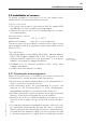
1B-8F-DC-4C-00-36
1B-8F-DC-4C-00-38
Channel 1
Channel 3
Channel 2
Channel 4
Installation and commissioning
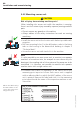
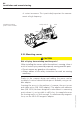
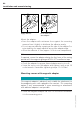
5.4.4 Connecting sensor unit
Note
The sensor cables must only be connected to the sensor unit after
the sensors have been installed, so that you have the option to
extend or shorten the cables if required (see also, “Installation of
sensors“, page 43).
• Open the sensor unit and feed the sensor cable through the
cable gland provided.
• Connect the four tinned cable strands to the respective terminals
for sensor 1 and sensor 2 (see also “Sensor unit: Overview of
connections and interfaces”, page 37).
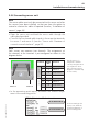
Note
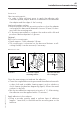
Each sensor can measure two channels. The assignment of
the channels to the terminals is pre-configured as shown in the
diagram below.
• In the measuring point report, document the channel assign-
ment of the measuring points.
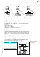
The left sensor 1 is
assigned to channels
1 and 3; the right sensor
2 is assigned to chan-
nels 2 and 4 (sectional
diagram of terminal strip
in sensor unit).
In the measuring point
report, note down the
channel assignment of
the measuring points.
Terminal
CHAN-
NEL
Function
Sensor 1
1 -- Power supply
2
1
Vibration
3
3
Temperature
4 -- GND
Sensor 2
13 -- Power supply
14
2
Vibration
15
4
Temperature
16 -- GND
Sensor 1 Sensor 2