
User's Manual


38
VIBCONNECT RF 11.2011
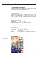
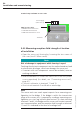
LEDs in sensor unit:
• GREEN: Data transmission
• YELLOW: Measurement
• RED: Data transmission error
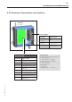
Terminal 1
Power supply
(24 V version)
Terminal strips and LEDs in sensor unit
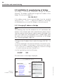
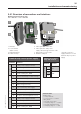
5.4.2 Measuring reception field strength at location
of installation
• Open the sensor unit housing by loosening the two screws of
the cover (size 2.5 Allen screws).
Note
Risk of damage to equipment while housing is open!
Touching the electronic components on the mother board can lead
to electrostatic discharge, which can damage the sensor unit.
» If contact with such components cannot be excluded, wear an
earthing wristband.
• Insert the batteries or connect the sensor unit to the 24 V power
source respectively (for details, see “Connecting sensor unit”,
page 41).
• Connect a voltmeter to terminals 11 and 12.
• Short-circuit terminals 5 and 6 with a wire bridge.
Note
The sensor unit now sends repeat requests for a measuring con-
figuration to the bridge. If the bridge is within the transmission
range of the sensor unit, it responds by sending a measuring con-
figuration or a test log without data content. By short-circuiting
terminals 5 and 6, the bridge and the sensor unit remain in perma-
nent communication, and the reception field strength at terminals
11 and 12 is indicated in the form of a voltage level.
Installation and commissioning