
User's Manual


37
VIBCONNECT RF 11.2011
2
3
4
6
5
1
8
7
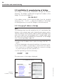
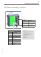
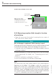
5.4.1 Overview of connections and interfaces
Battery-powered sensor unit
VIB 7.200-FBU or VIB 7.200-NBU
Installation and commissioning
1. Antenna
2. Cover fixtures
(Allen screws)
3. Lithium batteries
4. Terminal strip*
5. Cable gland for sensor line
6. Cable gland for 24V power
supply cable / energy harvester cable
7. Fixing tabs for sensor unit
8. Vibration dampers
* the 24 V version is
equipped with a second
terminal strip for power
supply
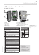
Technical data
Terminal strip:
• Crimp terminals
• Cross-section: < 0.5 mm²
Cable glands
• Size: M6 (sensor line)
• Clamping range: 2 ... 3.2 mm
• Size: M8 (24 V / harvester)
• Clamping range: 3 ... 5 mm
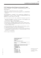
Terminal strip: sensor / power supply
Terminal Function
Sensor 1
1 5 VDC power supply (red wire)
2 Vibration signal (white wire)
3 Temperature signal (black wire)
4 Shield earthing line, GND
Energy harvester / commissioning
5 Short-circuit bridge (commissioning)
6 Short-circuit bridge (commissioning)
7 +8 V (energy harvester)
8 GND (energy harvester)
9 7– 9 V (external power supply)
10 GND (external power supply)
11 Reception field strength (0..1.25 V)
12 Reception field strength (0..1.25 V)
Sensor 2
13 5 VDC power supply (red wire)
14 Vibration signal (white wire)
15 Temperature signal (black wire)
16 Shield earthing line, GND
Additional terminal
strip, 24V version
Terminal Function
Power supply
1
24 V
2
3
GND
4