
User's Manual


33
VIBCONNECT RF 11.2011
T
y
p
e
S
e
t N
o
.
P
rü
ftech
n
ik A
G
P
.O
.B
ox 12
63
D
-8
045 Ism
a
n
in
g
Patends pending
Made in Germany
EEx ib IIC T4 - BVS No.93 XXXX
c
X
ENT
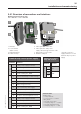
M
tools and materials
• Power drill, drill bit and thread cutter for M7 bolts
• M7 bolts and matching washers for fixture of bridge (4 bolts
per bridge)
• Open-end spanner of suitable size
• Open-end spanner (size 22) for M16 cable glands
• 3-wire electric cable of appropriate length for power supply line
• Ferrules for connection of power supply line
• Ring terminal for connection of earth conductor to PE
• Industrial Ethernet cable (CAT 5) for data of appropriate length
• Standard tools for electrical installation (wire cutter, cable stripper,
screwdriver)
• Suitable strain relief devices for cables
• If required: WLAN antenna extension cable (SMA)
CAUTION
Risk of injury from falling parts!
When installing a bridge at great height, there is a risk that the
bridge or a tool might fall to the ground, causing injury.
» Cordon off the area immediately below the installation site to
prevent access to the danger area.
» Use fall-arresting equipment.
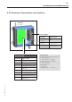
5.3.3 Mounting bridge
• Drill four holes at a suitable location of installation. For the drill
pattern, refer to the fixing tabs on the housing in the dimen-
sional drawing in chapter 3 “Technical data”.
• Secure the bridge with four bolts to the machine.
• If radio reception at the location of installation is poor, remove
the antenna from the housing and mount it in a suitable loca-
tion. To connect the antenna to the bridge, use a SMA cable of
appropriate length.
Note
Avoiding potential loops
If the antenna connection cable must be extended, ensure that
you do not inadvertently create a potential loop.
» The antenna cable must be installed so that potential differences
are avoided.
Installation and commissioning