
Installation and Operation Guide
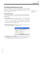

Table Of Contents
- Chapter 1: Introduction
- 1.1 First steps
- 1.2 Service addresses
- 1.3 About this manual
- Chapter 2: Safety
- 2.1 Safety symbols
- 2.2 Information for the system operator
- 2.3 Information for operating personnel
- 2.4 Intended use
- 2.5 Residual risks and safety measures
- Declaration of conformity
- Certifications
- Chapter 3: Technical data
- Chapter 4: System description
- 4.1 VIBCONNECT RF bridge
- 4.2 VIBCONNECT RF sensor unit
- 4.3 VIBCONNECT RF sensor
- Chapter 5: Installation & commissioning
- 5.1 Quick guide
- 5.2 Configuration in OMNITREND
- 5.3 Installation & commissioning of bridge
- 5.4 Installation & commissioning of sensor unit
- 5.5 Installation of sensors
- 5.6 Configuration in OMNITREND (continued)
- 5.7 Installing additional sensor unit
- Chapter 6: Maintenance
- 6.1 Cleaning
- 6.2 System time correction
- 6.3 Installation report
- 6.4 Battery-powered sensor unit
- 6.5 Update
- 6.6 Warranty
- 6.7 Spare parts and accessories
- Chapter 7: Troubleshooting
- Chapter 8: After use

69
VIBCONNECT RF 05.2012
Troubleshooting
CAUTION
Risk of injury from electric shock!
When carrying out installation, repair or maintenance work on the
power supply system of the bridge, there is a risk of injury from
electric shock (220 V voltage).
» All work on the power supply system must be carried out by
a qualified electrician.
» Disconnect the bridge from the power supply.
• If the firmware is damaged, the bridge will reboot after power
interruption in the 'Rescue Mode'. It is then only accessible via
the default IP address:
http://192.168.1.178/
In the main menu, you can only load a new firmware to the
bridge. After successful transfer, click on <Install Firmware> to
start the installation process and reboot the new bridge.
Note
If a fault cannot be rectified by any of the above measures, please
contact our technical support team (see also '1.2 Service ad-
dresses', page 5).