
Installation and Operation Guide
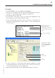
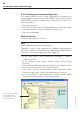
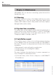
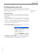
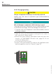
Table Of Contents
- Chapter 1: Introduction
- 1.1 First steps
- 1.2 Service addresses
- 1.3 About this manual
- Chapter 2: Safety
- 2.1 Safety symbols
- 2.2 Information for the system operator
- 2.3 Information for operating personnel
- 2.4 Intended use
- 2.5 Residual risks and safety measures
- Declaration of conformity
- Certifications
- Chapter 3: Technical data
- Chapter 4: System description
- 4.1 VIBCONNECT RF bridge
- 4.2 VIBCONNECT RF sensor unit
- 4.3 VIBCONNECT RF sensor
- Chapter 5: Installation & commissioning
- 5.1 Quick guide
- 5.2 Configuration in OMNITREND
- 5.3 Installation & commissioning of bridge
- 5.4 Installation & commissioning of sensor unit
- 5.5 Installation of sensors
- 5.6 Configuration in OMNITREND (continued)
- 5.7 Installing additional sensor unit
- Chapter 6: Maintenance
- 6.1 Cleaning
- 6.2 System time correction
- 6.3 Installation report
- 6.4 Battery-powered sensor unit
- 6.5 Update
- 6.6 Warranty
- 6.7 Spare parts and accessories
- Chapter 7: Troubleshooting
- Chapter 8: After use

65
VIBCONNECT RF 05.2012
* Measuring sequence =
2x vibration +
2x temperature
6.4 Battery-powered sensor unit
With normal operation, the lithium batteries of the sensor unit
last for about 3 years. Normal operation means one measuring
sequence* per hour and interference-free data transmission, at an
ambient temperature of 20 °C.
6.4.1 Battery status
The battery charge status is automatically transmitted by the sen-
sor unit together with the measurement data and displayed in
OMNITREND:
• At program start: If the battery charge at one of the sensor
units is too low, a warning is displayed when the OMNITREND
software is started. This warning is displayed at every program
start until the respective battery has been replaced and a new
measurement record has been read.
• Battery status report: In the main menu, select <Tools> / <Re-
ports> / <VIBCONNECT RF Battery Status>.
• Configuration of the bridge: In the configuration window for
the bridge, the battery charge status of each assigned sensor
unit is displayed (see section 'Configuration', page 57).
Maintenance