
Installation and Operation Guide
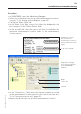
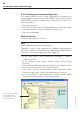
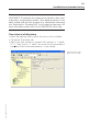
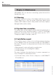
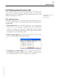
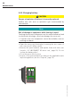
Table Of Contents
- Chapter 1: Introduction
- 1.1 First steps
- 1.2 Service addresses
- 1.3 About this manual
- Chapter 2: Safety
- 2.1 Safety symbols
- 2.2 Information for the system operator
- 2.3 Information for operating personnel
- 2.4 Intended use
- 2.5 Residual risks and safety measures
- Declaration of conformity
- Certifications
- Chapter 3: Technical data
- Chapter 4: System description
- 4.1 VIBCONNECT RF bridge
- 4.2 VIBCONNECT RF sensor unit
- 4.3 VIBCONNECT RF sensor
- Chapter 5: Installation & commissioning
- 5.1 Quick guide
- 5.2 Configuration in OMNITREND
- 5.3 Installation & commissioning of bridge
- 5.4 Installation & commissioning of sensor unit
- 5.5 Installation of sensors
- 5.6 Configuration in OMNITREND (continued)
- 5.7 Installing additional sensor unit
- Chapter 6: Maintenance
- 6.1 Cleaning
- 6.2 System time correction
- 6.3 Installation report
- 6.4 Battery-powered sensor unit
- 6.5 Update
- 6.6 Warranty
- 6.7 Spare parts and accessories
- Chapter 7: Troubleshooting
- Chapter 8: After use

63
VIBCONNECT RF 05.2012
Installation and commissioning
5.7 Installing additional sensor unit
VIBCONNECT RF can be extended at any time, and sensor units
and sensors can be added during operation of the system.
Setting up measurement locations and printing re-
ports
• Set up the required measurement locations in the OMNITREND
database (see also '5.2.2 Setting up the database', page 30).
• Print the measurement location report of the respective machine
train (see also '5.2.3 Creating and printing measurement loca-
tion report', page 31).
Installing sensor unit and sensors
• Identify a suitable location of installation for the sensor unit (see
also '5.4.2 Measuring reception field strength at location of in-
stallation', page 42).
• Mount the sensor unit on the machine.
• Mount the sensors (see also '5.5.2 Mounting sensor', page
48).
• Establish the electrical connections and commission the sensor
unit (see also '5.4.4 Connecting sensor unit', page 45).
• In the measurement location report, note down the machine on
which the sensor unit is installed (see also '5.4.3 Mounting sen-
sor unit', page 44). Also note down the channel to which the
respective measurement locations are connected (see also '5.4.4
Connecting sensor unit', page 45).
Configuring sensor unit in OMNITREND
• Register the sensor unit in OMNITREND.
• Assign the respective measurement locations set up in the ma-
chinery manager to the sensor unit and the bridge.
• Adjust the measuring channels according to the measurement
location report.
• Set up a measuring configuration for each measurement loca-
tion.
Transferring configuration and loading data
• Load the measuring configuration to the bridge (see also '5.6.5
Loading measuring configurations to the bridge', page 62).
• Import the measurement data in OMNITREND.