
Installation and Operation Guide
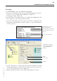
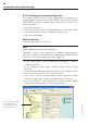
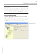
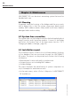
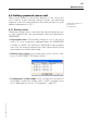
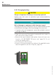
Table Of Contents
- Chapter 1: Introduction
- 1.1 First steps
- 1.2 Service addresses
- 1.3 About this manual
- Chapter 2: Safety
- 2.1 Safety symbols
- 2.2 Information for the system operator
- 2.3 Information for operating personnel
- 2.4 Intended use
- 2.5 Residual risks and safety measures
- Declaration of conformity
- Certifications
- Chapter 3: Technical data
- Chapter 4: System description
- 4.1 VIBCONNECT RF bridge
- 4.2 VIBCONNECT RF sensor unit
- 4.3 VIBCONNECT RF sensor
- Chapter 5: Installation & commissioning
- 5.1 Quick guide
- 5.2 Configuration in OMNITREND
- 5.3 Installation & commissioning of bridge
- 5.4 Installation & commissioning of sensor unit
- 5.5 Installation of sensors
- 5.6 Configuration in OMNITREND (continued)
- 5.7 Installing additional sensor unit
- Chapter 6: Maintenance
- 6.1 Cleaning
- 6.2 System time correction
- 6.3 Installation report
- 6.4 Battery-powered sensor unit
- 6.5 Update
- 6.6 Warranty
- 6.7 Spare parts and accessories
- Chapter 7: Troubleshooting
- Chapter 8: After use

61
VIBCONNECT RF 05.2012
Note
VIBCONNECT RF calculates the characteristic vibration values from
a spectrum, using frequency bands. These bands are preset in the
alarm wizard and are then assigned as a subordinate measuring
task ‘Bank analysis (Trending Task)’ to the respective spectrum. For
more information, please refer to the OMNITREND online help.
Time interval of idle phase
• Select the machine train in which the sensor unit is installed.
• Call up the ‘Train Data’ tab.
• Adjust the time interval as required (30 minutes to 1 week).
If ’t > 1 day’ and ‘t = 1 week’, also enter the time and day of
the week at which the measurement is to be started.
Time interval for idle
phase of sensor unit
Installation and commissioning