
Installation and Operation Guide
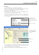
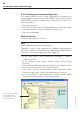
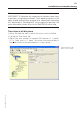
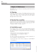
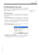
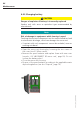
Table Of Contents
- Chapter 1: Introduction
- 1.1 First steps
- 1.2 Service addresses
- 1.3 About this manual
- Chapter 2: Safety
- 2.1 Safety symbols
- 2.2 Information for the system operator
- 2.3 Information for operating personnel
- 2.4 Intended use
- 2.5 Residual risks and safety measures
- Declaration of conformity
- Certifications
- Chapter 3: Technical data
- Chapter 4: System description
- 4.1 VIBCONNECT RF bridge
- 4.2 VIBCONNECT RF sensor unit
- 4.3 VIBCONNECT RF sensor
- Chapter 5: Installation & commissioning
- 5.1 Quick guide
- 5.2 Configuration in OMNITREND
- 5.3 Installation & commissioning of bridge
- 5.4 Installation & commissioning of sensor unit
- 5.5 Installation of sensors
- 5.6 Configuration in OMNITREND (continued)
- 5.7 Installing additional sensor unit
- Chapter 6: Maintenance
- 6.1 Cleaning
- 6.2 System time correction
- 6.3 Installation report
- 6.4 Battery-powered sensor unit
- 6.5 Update
- 6.6 Warranty
- 6.7 Spare parts and accessories
- Chapter 7: Troubleshooting
- Chapter 8: After use

60
VIBCONNECT RF 05.2012
5.6.4 Creating measuring configuration
This chapter explains how to create a measuring configuration for
a measurement location in the VIBCONNECT RF system, using the
OMNITREND software. A measuring configuration contains infor-
mation regarding
• the measuring tasks
• the time intervals at which measurements are to be performed
• the measurement location assigned to a sensor unit
• the associated bridge.
Measuring tasks
• Select a measurement location.
Note
Always observe the channel assignment:
Channels 1 and 2 are reserved for vibration measurements;
channels 3 and 4 are reserved for temperature measurements
(see also '5.4.4 Connecting sensor unit', page 45).
• In the main menu, select <Machinery Manager> / <Add> /
<Measuring Task>.
• In the measuring task dialog, activate option <Select Setup
Directly>.
• Select the applicable measuring task and click the <Next> button.
• In the next window, click the <Create> button.
• If you wish to set up another vibration measuring task, repeat
the above steps (max. 4 tasks per measurement location).
• For the calculation of the characteristic vibration values, define
the respective band analysis in the alarm wizard.
Installation and commissioning
The characteristic values
are calculated from
a spectrum by means
of “band analyses”