
Installation and Operation Guide
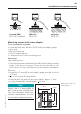
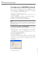
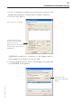
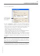
Table Of Contents
- Chapter 1: Introduction
- 1.1 First steps
- 1.2 Service addresses
- 1.3 About this manual
- Chapter 2: Safety
- 2.1 Safety symbols
- 2.2 Information for the system operator
- 2.3 Information for operating personnel
- 2.4 Intended use
- 2.5 Residual risks and safety measures
- Declaration of conformity
- Certifications
- Chapter 3: Technical data
- Chapter 4: System description
- 4.1 VIBCONNECT RF bridge
- 4.2 VIBCONNECT RF sensor unit
- 4.3 VIBCONNECT RF sensor
- Chapter 5: Installation & commissioning
- 5.1 Quick guide
- 5.2 Configuration in OMNITREND
- 5.3 Installation & commissioning of bridge
- 5.4 Installation & commissioning of sensor unit
- 5.5 Installation of sensors
- 5.6 Configuration in OMNITREND (continued)
- 5.7 Installing additional sensor unit
- Chapter 6: Maintenance
- 6.1 Cleaning
- 6.2 System time correction
- 6.3 Installation report
- 6.4 Battery-powered sensor unit
- 6.5 Update
- 6.6 Warranty
- 6.7 Spare parts and accessories
- Chapter 7: Troubleshooting
- Chapter 8: After use

58
VIBCONNECT RF 05.2012
Installation and commissioning
5.6.3 Assigning measurement locations in the data-
base to a sensor unit and bridge
The measurement location report contains all information regard-
ing the assignment of channels to measurement locations. The
respective sensor units are identified in OMNITREND by means of
their MAC address.
In systems with several bridges, you can assign the sensor units to
any available bridge. However, the following issues should be kept
in mind for proper assignment:
• Select the bridge with the best reception: At every bridge select
“RF Sensor Units” in the main menu, and check the receive level
of the sensor unit you wish to assign (see also '5.3.1 Changing
IP address of bridge', page 32).
• Maximum 50 sensor units can be assigned to each bridge.