
Installation and Operation Guide
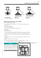
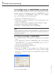
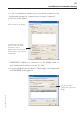
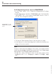
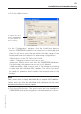
Table Of Contents
- Chapter 1: Introduction
- 1.1 First steps
- 1.2 Service addresses
- 1.3 About this manual
- Chapter 2: Safety
- 2.1 Safety symbols
- 2.2 Information for the system operator
- 2.3 Information for operating personnel
- 2.4 Intended use
- 2.5 Residual risks and safety measures
- Declaration of conformity
- Certifications
- Chapter 3: Technical data
- Chapter 4: System description
- 4.1 VIBCONNECT RF bridge
- 4.2 VIBCONNECT RF sensor unit
- 4.3 VIBCONNECT RF sensor
- Chapter 5: Installation & commissioning
- 5.1 Quick guide
- 5.2 Configuration in OMNITREND
- 5.3 Installation & commissioning of bridge
- 5.4 Installation & commissioning of sensor unit
- 5.5 Installation of sensors
- 5.6 Configuration in OMNITREND (continued)
- 5.7 Installing additional sensor unit
- Chapter 6: Maintenance
- 6.1 Cleaning
- 6.2 System time correction
- 6.3 Installation report
- 6.4 Battery-powered sensor unit
- 6.5 Update
- 6.6 Warranty
- 6.7 Spare parts and accessories
- Chapter 7: Troubleshooting
- Chapter 8: After use

56
VIBCONNECT RF 05.2012
Installation and commissioning
5.6.2 Registering sensor units in OMNITREND
• In the main menu, click <Options> / <Registration / Configu-
ration>.
• In the ‘Registration’ window (‘OMNITREND’ tab), check whether
‘VIBCONNECT RF’ is the current OMNITREND version. If this is
not the case, change the settings.
• Call up the ‘Measurement Device’ tab (see previous page).
• In the device list, select the bridge that is within the transmission
range of the sensor unit(s).
Note
If there is more than one bridge in the system, you might need to
check for every bridge whether the sensor unit is in its radio range
and whether it has already established contact.
» To do this, select “RF Sensor Units” in the main menu of the
bridge(see also '5.3.1 Changing IP address of bridge', page
32).
OMNITREND for 'VIB-
CONNECT RF' must be
active.