
Installation and Operation Guide
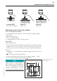
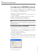
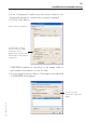
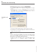
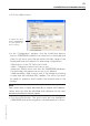
Table Of Contents
- Chapter 1: Introduction
- 1.1 First steps
- 1.2 Service addresses
- 1.3 About this manual
- Chapter 2: Safety
- 2.1 Safety symbols
- 2.2 Information for the system operator
- 2.3 Information for operating personnel
- 2.4 Intended use
- 2.5 Residual risks and safety measures
- Declaration of conformity
- Certifications
- Chapter 3: Technical data
- Chapter 4: System description
- 4.1 VIBCONNECT RF bridge
- 4.2 VIBCONNECT RF sensor unit
- 4.3 VIBCONNECT RF sensor
- Chapter 5: Installation & commissioning
- 5.1 Quick guide
- 5.2 Configuration in OMNITREND
- 5.3 Installation & commissioning of bridge
- 5.4 Installation & commissioning of sensor unit
- 5.5 Installation of sensors
- 5.6 Configuration in OMNITREND (continued)
- 5.7 Installing additional sensor unit
- Chapter 6: Maintenance
- 6.1 Cleaning
- 6.2 System time correction
- 6.3 Installation report
- 6.4 Battery-powered sensor unit
- 6.5 Update
- 6.6 Warranty
- 6.7 Spare parts and accessories
- Chapter 7: Troubleshooting
- Chapter 8: After use

54
VIBCONNECT RF 05.2012
5.6 Configuration in OMNITREND (continued)
After the system components have been installed and commis-
sioned, continue configuring the system in OMNITREND (see also
'5.2 Configuration in OMNITREND', page 29). The configura-
tion consists mainly of the following steps:
• Registration of bridge and sensor units
• Assignment of system components to the measurement loca-
tions in the database
• Creation of measuring configurations and loading to bridge
• Reading of measurement data from bridge
• Evaluation of measurement data in OMNITREND
Note
These instructions assume that the operator is familiar with the
OMNITREND software and its features The instructions below are
therefore kept brief.
5.6.1 Registering bridge in OMNITREND
• In the main menu, click <Options> / <Registration / Configura-
tion>.
• In the ‘Registration’ window (‘OMNITREND’ tab), check whether
‘VIBCONNECT RF’ is the current OMNITREND version. If this is
not the case, change the settings.
• Call up the ‘Measurement Device’ tab.
• Click the <Get ID> button.
• Enter the IP address of the bridge in the ‘Ethernet Setup’
window(see also '5.3 Installation & commissioning of bridge',
page 32). If required, adjust the Subnet Mask and the Gate-
way address.
• Click the <OK> button.
Installation and commissioning