
Installation and Operation Guide
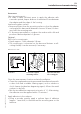
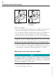
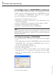
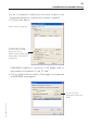
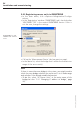
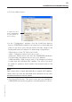
Table Of Contents
- Chapter 1: Introduction
- 1.1 First steps
- 1.2 Service addresses
- 1.3 About this manual
- Chapter 2: Safety
- 2.1 Safety symbols
- 2.2 Information for the system operator
- 2.3 Information for operating personnel
- 2.4 Intended use
- 2.5 Residual risks and safety measures
- Declaration of conformity
- Certifications
- Chapter 3: Technical data
- Chapter 4: System description
- 4.1 VIBCONNECT RF bridge
- 4.2 VIBCONNECT RF sensor unit
- 4.3 VIBCONNECT RF sensor
- Chapter 5: Installation & commissioning
- 5.1 Quick guide
- 5.2 Configuration in OMNITREND
- 5.3 Installation & commissioning of bridge
- 5.4 Installation & commissioning of sensor unit
- 5.5 Installation of sensors
- 5.6 Configuration in OMNITREND (continued)
- 5.7 Installing additional sensor unit
- Chapter 6: Maintenance
- 6.1 Cleaning
- 6.2 System time correction
- 6.3 Installation report
- 6.4 Battery-powered sensor unit
- 6.5 Update
- 6.6 Warranty
- 6.7 Spare parts and accessories
- Chapter 7: Troubleshooting
- Chapter 8: After use

51
VIBCONNECT RF 05.2012
Installation and commissioning
installation
Select mounting point:
• In order to have sufficient space to apply the adhesive with
a wooden spatula, keep a distance of minimum 35 mm between
the adapter and the edges of the housing.
Level and roughen surface:
• Remove all paint from the mounting surface so that the adapter
can be glued to bare metal (diameter of area > 30 mm). If neces-
sary, level the mounting area.
• To ensure proper adhesion, roughen the surface with a file and
produce a diamond pattern of grooves.
Optional:
Drill hole for securing pin.
• Depth: approx. 5 mm; diameter 3.6 mm.
• The securing pin is mounted on the base and features a self-
cutting thread; it can be removed, if necessary.
Clean the measurement location and mix the adhesive:
• Clean the roughened mounting area and the adhesive base with
a clean cloth and a suitable cleaning agent, such as a brake or
clutch cleaner (residue-free degreasing agent). Allows the metal
surfaces to dry fully.
• Mix the two adhesive components at a ratio of 1:1. After mixing,
the adhesive must be applied within 15 minutes!
Apply adhesive to the surfaces:
• Using a wooden spatula, apply a uniform layer of adhesive
(approx. 1 mm thick) to the base and the mounting area on the
machine.
Clearance
> 35 mm
Level and roughen
mounting surface
Optional: Drill hole
for securing pin
30
5
3,6
Dimensions in mm