
Installation and Operation Guide

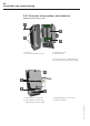
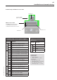
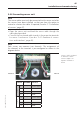
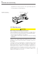
Table Of Contents
- Chapter 1: Introduction
- 1.1 First steps
- 1.2 Service addresses
- 1.3 About this manual
- Chapter 2: Safety
- 2.1 Safety symbols
- 2.2 Information for the system operator
- 2.3 Information for operating personnel
- 2.4 Intended use
- 2.5 Residual risks and safety measures
- Declaration of conformity
- Certifications
- Chapter 3: Technical data
- Chapter 4: System description
- 4.1 VIBCONNECT RF bridge
- 4.2 VIBCONNECT RF sensor unit
- 4.3 VIBCONNECT RF sensor
- Chapter 5: Installation & commissioning
- 5.1 Quick guide
- 5.2 Configuration in OMNITREND
- 5.3 Installation & commissioning of bridge
- 5.4 Installation & commissioning of sensor unit
- 5.5 Installation of sensors
- 5.6 Configuration in OMNITREND (continued)
- 5.7 Installing additional sensor unit
- Chapter 6: Maintenance
- 6.1 Cleaning
- 6.2 System time correction
- 6.3 Installation report
- 6.4 Battery-powered sensor unit
- 6.5 Update
- 6.6 Warranty
- 6.7 Spare parts and accessories
- Chapter 7: Troubleshooting
- Chapter 8: After use

47
VIBCONNECT RF 05.2012
5.5 Installation of sensors
For proper installation of the sensors on site, the operator must
ensure that the following requirements are met:
location of installation
• The sensors are secured to the machine with the supplied M8
threaded bolt or with a suitable mounting adapter.
• Observe the rules for the choice of measurement locations for
vibration measurements.
Permissible ambient conditions
Temperature: – 40 °C to +125 °C
Relative air humidity: max. 95 %, non-condensing
The sensors must not be installed in a location that is near a strong
electromagnetic field (e.g. generator, high-voltage cable, electric
drive unit, etc.).
tools and materials
• Mounting adapter: Screw adapter (VIB 3.480*), adhesive adapter
(VIB 3.418), magnetic adapter (VIB 3.423). For special tools and
auxiliary materials required for the attachment of the various
adapters, see chapter for adapter installation.
• Standard tools for electrical installation (wire cutter, cable
stripper, screwdriver).
• Suitable strain relief devices for cables.
5.5.1 Choosing the measurement locations
When choosing a location of installation for a sensor observe the
following rules to ensure optimum signal transmission:
• Mount sensor in radial measuring direction (i.e. perpendicular to
shaft, in vertical or horizontal position).
• Axial measurement locations are recommended to monitor
the machine for the following defects or faults: Misalignment,
damaged geared wheels, loose fixtures, bent shafts, etc.
• Machines mounted on rigid foundations show high horizontal
vibration. Fixed anchoring suppresses vertical vibration.
• Machines mounted on vibration-damped foundations show
vibration that is equally strong in horizontal and vertical direc-
tion.
• The frequency behavior and dynamic range of the sensor can
be significantly influenced by the way the sensor is attached.
Weak coupling to the measurement location results in attenu-
ated signals and limits the frequency range. The sensor must be
secured to the measurement location in a rigid, friction-locked
Installation and commissioning
* included in
scope of delivery