
Installation and Operation Guide

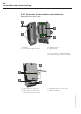
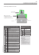
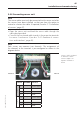
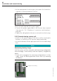
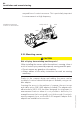
Table Of Contents
- Chapter 1: Introduction
- 1.1 First steps
- 1.2 Service addresses
- 1.3 About this manual
- Chapter 2: Safety
- 2.1 Safety symbols
- 2.2 Information for the system operator
- 2.3 Information for operating personnel
- 2.4 Intended use
- 2.5 Residual risks and safety measures
- Declaration of conformity
- Certifications
- Chapter 3: Technical data
- Chapter 4: System description
- 4.1 VIBCONNECT RF bridge
- 4.2 VIBCONNECT RF sensor unit
- 4.3 VIBCONNECT RF sensor
- Chapter 5: Installation & commissioning
- 5.1 Quick guide
- 5.2 Configuration in OMNITREND
- 5.3 Installation & commissioning of bridge
- 5.4 Installation & commissioning of sensor unit
- 5.5 Installation of sensors
- 5.6 Configuration in OMNITREND (continued)
- 5.7 Installing additional sensor unit
- Chapter 6: Maintenance
- 6.1 Cleaning
- 6.2 System time correction
- 6.3 Installation report
- 6.4 Battery-powered sensor unit
- 6.5 Update
- 6.6 Warranty
- 6.7 Spare parts and accessories
- Chapter 7: Troubleshooting
- Chapter 8: After use

42
VIBCONNECT RF 05.2012
5.4.2 Measuring reception field strength at location
of installation
Note
Radio approval
The antenna on the sensor unit is installed at the factory and must
not be removed.
» Contact PRÜFTECHNIK, if you want to use a different type of
antenna or if you need to extend the original antenna from an
enclosure with an antenna cable.
Note
Risk of damage to equipment while housing is open!
Touching the electronic components on the mother board can lead
to electrostatic discharge, which can damage the sensor unit.
» If contact with such components cannot be excluded, wear an
earthing wristband.
• Adjust the antenna roughly.
• Open the sensor unit housing by loosening the two screws of
the cover (size 2.5 Allen screws).
• Insert the batteries or connect the sensor unit to the 24 V power
source respectively (see also '5.4.4 Connecting sensor unit',
page 45).
• Connect a voltmeter to terminals 11 and 12.
• Short-circuit terminals 5 and 6 with a wire bridge.
Note
The sensor unit now sends repeat requests for a measuring con-
figuration to the bridge. If the bridge is within the transmission
range of the sensor unit, it responds by sending a measuring con-
figuration or a test log without data content. By short-circuiting
terminals 5 and 6, the bridge and the sensor unit remain in perma-
nent communication, and the reception field strength at terminals
11 and 12 is indicated in the form of a voltage level.
• Check the voltage at the eligible locations of installation. Wait for
approx. 3 – 4 seconds until the reception /voltage has stabilized.
U > 0.1 V: Reception OK
U
max.
= 1.25 V
Installation and commissioning