
Installation and Operation Guide
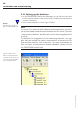
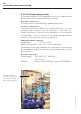
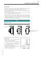
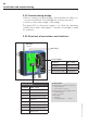
Table Of Contents
- Chapter 1: Introduction
- 1.1 First steps
- 1.2 Service addresses
- 1.3 About this manual
- Chapter 2: Safety
- 2.1 Safety symbols
- 2.2 Information for the system operator
- 2.3 Information for operating personnel
- 2.4 Intended use
- 2.5 Residual risks and safety measures
- Declaration of conformity
- Certifications
- Chapter 3: Technical data
- Chapter 4: System description
- 4.1 VIBCONNECT RF bridge
- 4.2 VIBCONNECT RF sensor unit
- 4.3 VIBCONNECT RF sensor
- Chapter 5: Installation & commissioning
- 5.1 Quick guide
- 5.2 Configuration in OMNITREND
- 5.3 Installation & commissioning of bridge
- 5.4 Installation & commissioning of sensor unit
- 5.5 Installation of sensors
- 5.6 Configuration in OMNITREND (continued)
- 5.7 Installing additional sensor unit
- Chapter 6: Maintenance
- 6.1 Cleaning
- 6.2 System time correction
- 6.3 Installation report
- 6.4 Battery-powered sensor unit
- 6.5 Update
- 6.6 Warranty
- 6.7 Spare parts and accessories
- Chapter 7: Troubleshooting
- Chapter 8: After use

35
VIBCONNECT RF 05.2012
T
y
p
e
S
e
t
N
o
.
Pr
üf
t
ech
nik
A
G
P.
O.
B
ox
1
26
3
D-
8
04
5 I
s
m
an
ing
Patends pending
Made in Germany
EEx ib IIC T4 - BVS No.93 XXXX
c
X
ENT
M
tools and materials
• Power drill, drill bit and thread cutter for M7 bolts
• M7 bolts and matching washers for fixture of bridge (4 bolts
per bridge)
• Open-end spanner of suitable size
• Open-end spanner (size 22) for M16 cable glands
• 3-wire electric cable of appropriate length for power supply line
• Ferrules for connection of power supply line
• Industrial Ethernet cable (CAT 5) for data of appropriate length
• Standard tools for electrical installation (wire cutter, cable stripper,
screwdriver)
• Suitable strain relief devices for cables
• If required: WLAN antenna extension cable (SMA, 50 ohm)
CAUTION
Risk of injury from falling parts!
When installing a bridge at great height, there is a risk that the
bridge or a tool might fall to the ground, causing injury.
» Cordon off the area immediately below the installation site to
prevent access to the danger area.
» Use fall-arresting equipment.
5.3.3 Mounting bridge
• Drill four holes at a suitable location of installation. For the drill
pattern, refer to the fixing tabs on the housing in the dimen-
sional drawing in chapter 3 “Technical data”.
• Secure the bridge with four bolts to the machine.
• Adjust the antenna roughly.
Note
Radio approval
The antenna on the bridge is installed at the factory and must not
be removed.
» Contact PRÜFTECHNIK, if you want to use a different type of
antenna or if you need to extend the original antenna from an
enclosure with an antenna cable.
Installation and commissioning