
Installation and Operation Guide
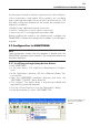
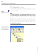
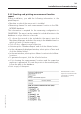
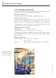
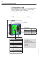
Table Of Contents
- Chapter 1: Introduction
- 1.1 First steps
- 1.2 Service addresses
- 1.3 About this manual
- Chapter 2: Safety
- 2.1 Safety symbols
- 2.2 Information for the system operator
- 2.3 Information for operating personnel
- 2.4 Intended use
- 2.5 Residual risks and safety measures
- Declaration of conformity
- Certifications
- Chapter 3: Technical data
- Chapter 4: System description
- 4.1 VIBCONNECT RF bridge
- 4.2 VIBCONNECT RF sensor unit
- 4.3 VIBCONNECT RF sensor
- Chapter 5: Installation & commissioning
- 5.1 Quick guide
- 5.2 Configuration in OMNITREND
- 5.3 Installation & commissioning of bridge
- 5.4 Installation & commissioning of sensor unit
- 5.5 Installation of sensors
- 5.6 Configuration in OMNITREND (continued)
- 5.7 Installing additional sensor unit
- Chapter 6: Maintenance
- 6.1 Cleaning
- 6.2 System time correction
- 6.3 Installation report
- 6.4 Battery-powered sensor unit
- 6.5 Update
- 6.6 Warranty
- 6.7 Spare parts and accessories
- Chapter 7: Troubleshooting
- Chapter 8: After use

30
VIBCONNECT RF 05.2012
5.2.2 Setting up the database
• In the OMNITREND Machinery Manager, set up the tree structure
for the machine park to be monitored, including a measurement
location hierarchy.
• Select measurement location type ‘Online’.
Note
If a sensor is to measure both vibration and temperature, you must
set up two separate measurement locations for this sensor. The term
“measurement location” actually refers to the measuring channel of
a sensor.
To facilitate the assignment of the measuring channels, we sug-
gest that you include the type of measurement in the name of the
measurement location (see screenshot). For more information on
how to create a measurement location database, please refer to
the OMNITREND online help.
Typical machine tree
with four measurement
locations at the motor for
one sensor unit (2x vibra-
tion, 2x temperature).
Installation and commissioning
Online
Measurement location
type for VIBCONNECT RF