
Installation and Operation Guide
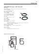
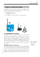
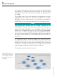
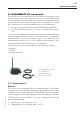
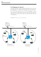
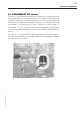
Table Of Contents
- Chapter 1: Introduction
- 1.1 First steps
- 1.2 Service addresses
- 1.3 About this manual
- Chapter 2: Safety
- 2.1 Safety symbols
- 2.2 Information for the system operator
- 2.3 Information for operating personnel
- 2.4 Intended use
- 2.5 Residual risks and safety measures
- Declaration of conformity
- Certifications
- Chapter 3: Technical data
- Chapter 4: System description
- 4.1 VIBCONNECT RF bridge
- 4.2 VIBCONNECT RF sensor unit
- 4.3 VIBCONNECT RF sensor
- Chapter 5: Installation & commissioning
- 5.1 Quick guide
- 5.2 Configuration in OMNITREND
- 5.3 Installation & commissioning of bridge
- 5.4 Installation & commissioning of sensor unit
- 5.5 Installation of sensors
- 5.6 Configuration in OMNITREND (continued)
- 5.7 Installing additional sensor unit
- Chapter 6: Maintenance
- 6.1 Cleaning
- 6.2 System time correction
- 6.3 Installation report
- 6.4 Battery-powered sensor unit
- 6.5 Update
- 6.6 Warranty
- 6.7 Spare parts and accessories
- Chapter 7: Troubleshooting
- Chapter 8: After use

28
VIBCONNECT RF 05.2012
Installation and commissioning
Chapter 5: Installation & commissioning
5.1 Quick guide
5.1.1 Initial installation of system / radio cell
In OMNITREND at PC workstation
• Register device driver
• Set up measurement location database
• Print measurement location report
• Adjust IP address at the bridge
On site
• Install and start bridge
• Install sensor unit
• Install sensors and connect them to the sensor unit
• Enter the following data in the measurement location report: MAC ad-
dress of sensor unit, measuring channel, measurement location
• Start sensor unit
• For additional sensor units, perform steps 6 to 9
In OMNITREND
• Register bridge in OMNITREND
• Register sensor units in OMNITREND
• Assign measurement locations to the bridge and the sensor unit
(see measurement location report)
• Configure measuring channels (see measurement location report)
• Create measuring configuration for each measuring channel
• Load measuring configurations to the bridge
• Import first measurement data in OMNITREND
5.1.2 Subsequent installation of additional sensor unit
In OMNITREND
• Add new measurement locations to the measurement location database
• Print measurement location report for the respective machine section
On site
• Install sensor unit
• Install sensors and connect them to the sensor unit
• Enter the following data in the measurement location report: measuring
channel, measurement location, MAC address of sensor unit
• Start sensor unit
In OMNITREND
• Register sensor unit in OMNITREND
• Assign measurement locations to the bridge and the sensor unit
(see measurement location report)
• Configure measuring channels (see measurement location report)
• Create measuring configuration for each measuring channel
• Load measuring configurations to the bridge
• Import first measurement data in OMNITREND