
Installation and Operation Guide
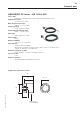
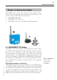
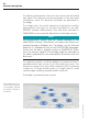
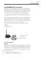
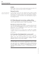
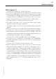
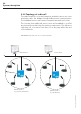
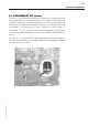
Table Of Contents
- Chapter 1: Introduction
- 1.1 First steps
- 1.2 Service addresses
- 1.3 About this manual
- Chapter 2: Safety
- 2.1 Safety symbols
- 2.2 Information for the system operator
- 2.3 Information for operating personnel
- 2.4 Intended use
- 2.5 Residual risks and safety measures
- Declaration of conformity
- Certifications
- Chapter 3: Technical data
- Chapter 4: System description
- 4.1 VIBCONNECT RF bridge
- 4.2 VIBCONNECT RF sensor unit
- 4.3 VIBCONNECT RF sensor
- Chapter 5: Installation & commissioning
- 5.1 Quick guide
- 5.2 Configuration in OMNITREND
- 5.3 Installation & commissioning of bridge
- 5.4 Installation & commissioning of sensor unit
- 5.5 Installation of sensors
- 5.6 Configuration in OMNITREND (continued)
- 5.7 Installing additional sensor unit
- Chapter 6: Maintenance
- 6.1 Cleaning
- 6.2 System time correction
- 6.3 Installation report
- 6.4 Battery-powered sensor unit
- 6.5 Update
- 6.6 Warranty
- 6.7 Spare parts and accessories
- Chapter 7: Troubleshooting
- Chapter 8: After use

24
VIBCONNECT RF 05.2012
24 VDC
For this type of sensor unit, the system operator must provide a 24
VDC power connection at the location of installation.
Energy harvester
For this type of sensor unit, the operator must install an energy
harvester (VIB 7.210-xxx*) that converts the vibration energy of
the machine into electric power. This can only be done, if the ma-
chine speed is constant and within the useful frequency range of
the energy harvester.
4.2.2 Operating cycle: measuring, sending, idling
The sensor unit performs the measuring tasks at preset intervals,
sends the data and then returns to idle to save energy.
Measuring time, transmission time, idle time
Each measuring sequence takes about 3 seconds, while the send-
ing of the data might take up to 30 seconds. The duration of the
idle phase is set in OMNITREND for each sensor unit to a time
between 30 minutes and 1 week.
To explain the function of a sensor unit in a radio cell, a number
of typical scenarios are described below in the form of questions
and answers.
4.2.3 How does the bridge detect a sensor unit?
Each sensor unit is assigned a unique code, known as the MAC
address. This code is pre-programmed in the radio module and
cannot be altered. A sensor unit is assigned to a bridge in the OM-
NITREND software, using its MAC address.
Note
The MAC address of a sensor unit is engraved in its cover. In addi-
tion, each sensor unit is equipped with an adhesive label bearing
the MAC address that is used for the configuration of the mea-
surement location database (see also '5.4.3 Mounting sensor unit',
page 44).
System description
*xxx = 50, 60, 100, 120
(frequency range in Hz)