
Installation and Operation Guide
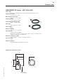
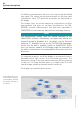
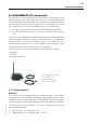
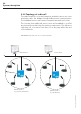
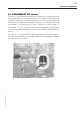
Table Of Contents
- Chapter 1: Introduction
- 1.1 First steps
- 1.2 Service addresses
- 1.3 About this manual
- Chapter 2: Safety
- 2.1 Safety symbols
- 2.2 Information for the system operator
- 2.3 Information for operating personnel
- 2.4 Intended use
- 2.5 Residual risks and safety measures
- Declaration of conformity
- Certifications
- Chapter 3: Technical data
- Chapter 4: System description
- 4.1 VIBCONNECT RF bridge
- 4.2 VIBCONNECT RF sensor unit
- 4.3 VIBCONNECT RF sensor
- Chapter 5: Installation & commissioning
- 5.1 Quick guide
- 5.2 Configuration in OMNITREND
- 5.3 Installation & commissioning of bridge
- 5.4 Installation & commissioning of sensor unit
- 5.5 Installation of sensors
- 5.6 Configuration in OMNITREND (continued)
- 5.7 Installing additional sensor unit
- Chapter 6: Maintenance
- 6.1 Cleaning
- 6.2 System time correction
- 6.3 Installation report
- 6.4 Battery-powered sensor unit
- 6.5 Update
- 6.6 Warranty
- 6.7 Spare parts and accessories
- Chapter 7: Troubleshooting
- Chapter 8: After use

21
VIBCONNECT RF 05.2012
2
3
1
Chapter 4: System description
VIBCONNECT RF is a stationary, wireless online condition moni-
toring system designed for easy installation and operation. The
system consists of the following components:
1. VIBCONNECT RF bridge
2. VIBCONNECT RF sensor unit
3. VIBCONNECT RF sensor for vibration and temperature
4.1 VIBCONNECT RF bridge
The bridge is the central reception and transmission unit in a wire-
less network (star topology) that can include up to 50 sensor units
(see also '4.2.4 Topology of radio cell', page 26). It receives
the measurements from the sensor unit(s), processes them and
transfers them to the OMNITREND software for evaluation and
archiving. The bridge is supplied by the OMNITREND software with
the measuring configurations* for each measurement location
and forwards this information via radio signal to the respective
sensor units.
Detailed description of function
OMNITREND loads the measuring configurations to the bridge, which
is connected through a patch cable to the local network. The bridge
then transmits this information via radio signal to the respective sen-
sor units. This happens as soon as these sensor units signal to the
bridge that they are active. The data transfer is bidirectional, i.e. the
bridge can only communicate with one sensor unit at any one time.
System description
* Meas. configu ration =
measuring task +
trigger settings +
band analysis
(if required)